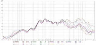
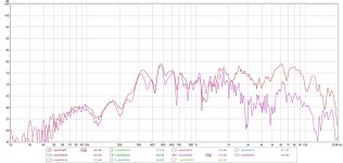
Here's some measurements. One with five degree increments, 0 to 40 degrees with lots of smoothing, the other of 0 and 30 degrees with 1/48 octave smoothing. No EQ. Sound is still changing, these measurements might look different after further loosening up. Already sounding nice. Nice tweeters for my BiB. 😀
Attachments
I've searched this thread for information on how to figure out the optimal clearance between horn opening and ceiling or floor in a corner-loaded BIB and haven't found any. Please point me to the info if it's already here, but if not, I thought I'd open this for discussion.
Maybe there is no optimal clearance, so any experience or general guidelines would be appreciated too.
My best guess is that, since the BIB uses the room boundaries to continue the horn, the distance from horn mouth to ceiling would ideally be equal to the front-back length of the mouth, just like where the a-b-c distances are all equal at the horn fold in a traditional BIB.
Am I way off?
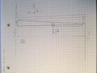
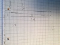
Reason I ask is that I'm considering building a pair of corner-loaded BIBs in a room with 8 foot ceilings, using either FE103Sol or FF105WK (I plugged the manufacturer data into the spreadsheets from Zilla's website). Due to the cabinet heights of either of these, a traditional folded BIB would need to be inverted.
Otherwise, it would be possible to do an unfolded ceiling-firing BIB (drawings attached). In that configuration, an FE103Sol BIB would have about 15.5 inches of clearance between horn mouth and ceiling (possibly too much?), while an FF105WK would have about 4.85 inches (possibly too little?).
Just wondering what the thoughts are on this.
Maybe there is no optimal clearance, so any experience or general guidelines would be appreciated too.
My best guess is that, since the BIB uses the room boundaries to continue the horn, the distance from horn mouth to ceiling would ideally be equal to the front-back length of the mouth, just like where the a-b-c distances are all equal at the horn fold in a traditional BIB.
Am I way off?
Reason I ask is that I'm considering building a pair of corner-loaded BIBs in a room with 8 foot ceilings, using either FE103Sol or FF105WK (I plugged the manufacturer data into the spreadsheets from Zilla's website). Due to the cabinet heights of either of these, a traditional folded BIB would need to be inverted.
Otherwise, it would be possible to do an unfolded ceiling-firing BIB (drawings attached). In that configuration, an FE103Sol BIB would have about 15.5 inches of clearance between horn mouth and ceiling (possibly too much?), while an FF105WK would have about 4.85 inches (possibly too little?).
Just wondering what the thoughts are on this.
Attachments
Bookmarked! Thank you.
To try an example: the terminus for FE103Sol would be 8.186" x 5.788" (according to the spreadsheet). Using your formula...
******************
Ec = Rp*0.613
where:
Rp = pipe/terminus radius
Example:
terminus is 15" x 10.6":
Ec = 0.613*[15*10.6/pi]^0.5 = 4.36"
******************
... with the FE103Sol spreadsheet numbers, we get:
Ec = 0.613*[8.186*5.788/pi]^0.5
8.186*5.788/pi = 15.0893
15.0893^0.5= 3.8845
3.8845 * 0.613 = 2.38"
2.38" is very close to the ceiling, much less space than I would have guessed -- seems like a mass-loading distance to my untrained instinct.
For FF105WK, the resulting Ec = 2.275"
In that case, the FF105WK might be the better candidate (from the construction point of view), since I'd need to add less to the base in order to get the proper mouth-to-ceiling spacing and driver height would be more optimal at about 40" off the ground, really pretty good actually.
So it would seem that the choice is between unfolded FF105WK BIB or FE103Sol inverted BIB (or even Planet 10's inverted BIB with Karlson slot).
Last edited:
As I mentioned in your other thread, you don’t need to add a base; just tune it to a lower Fs until you get the gap to the ceiling you want. And err on the side of a larger box, ie keep width and depth the same while increasing length.
At least this is what I have understood from GM’s earlier posts on the subject. 🙂
At least this is what I have understood from GM’s earlier posts on the subject. 🙂
Last edited:
Hi GM,
In the post you refer to, you say that using a top hat is an alternative to changing the effective length of the box. Wouldn't using a top hat defeat the corner loading effect we want to reach?
I mean, we put a solid wall (small but a wall anyway) between the terminus and the top corner of the room and get the driver loaded as desired but isn't the transmission effect defeated in a significant way?
Gastón
I am the least knowledgeable guy here. I do remember that when I once read this thread a number of years ago, there was someone who tried their BIB in two different rooms with two different ceiling heights. I don't remember who it was or what driver it was. I do remember him posting that he started out playing his BIB's in a room with a 7 foot ceiling. He was very happy with the results and decided to move his BIB into a room with a 9 foot ceiling. In the room with the 9 foot ceiling he was disappointed and their was no bass. So, he moved the BIB's back into the room with the 7 foot ceiling and lived happily ever after. That is my recollection without searching this very long and ever growing thread.
Thanks, everyone. This has been very helpful. Perhaps we should consolidate the key info in this thread on the wiki, so people don't have to keep asking?
Wouldn't using a top hat defeat the corner loading effect we want to reach?
.......isn't the transmission effect defeated in a significant way?
Greets!
I guess it depends on what one considers 'significant' as it alters it from a pipe horn to a mass loaded expanding TL [ML-horn] since the top hat is a very large vent acoustically.
No experience with an expanding TL beyond seeing a worthwhile result in Hornresp
even without it being able to do a proper wall/corner/ceiling loading, but did it with great success on many TQWTs [inverse tapered] to smooth out, lower tuning, hence requiring less stuffing, greater acoustic efficiency.
I posted one such design including a build sketch using a 6.5"? RadioShack 'FR' driver on the late, lamented 'full-range' forum, but AFAIK no one tried it, so with none to critique it, haven't promoted it further except for the BIB top hat variant.
All that said, somewhere I've posted that the theoretically correct way to make it taller is to continue its expansion, making [Sm] larger in the process. Since I don't know a way to calculate it with the Excel designer, it will require drawing it out to scale or using geometry to find it and maybe winding up with an unacceptable driver offset.
GM
Thanks, everyone.
You're welcome!
Yeah, I had it all collected on a WORD doc for quick reference since the beginning with my PMs with Terry before he built/posted his on the other forum, but it's now locked up on two damaged hard drives, so now only have a small portion on gmail email drafts.
GM
There is a lot in this thread. Its use depends on context, so I kind of like that you have to read and search the thread for the things you need in a particular situation.
But that's me. In the dark ages I would have been a hermit monk. ;-)
But that's me. In the dark ages I would have been a hermit monk. ;-)
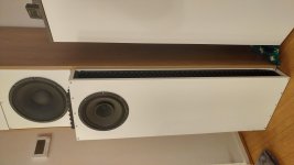
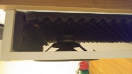
I am planning a new BIB build. After honest reflection, the current 12" BIB is not an efficient use of space. It's not so much too large, but it sticks into the room, the mid-high section sticks out and because that needs to be angled, it's not flush in the corner. I was going to build a second one, but wondered if I could do better.
I am calculating and simulating with two Tangbang W69-1042 drivers per side. Using Vas/1.44, that needs about 280-290 liters. I can achieve that with standard boards, creating a BIB tuned to their FS of 35 Hz. It would be 60cm wide and 23.6 cm deep (20 cm wide board, 1.8 mm thickness). Obviously, this would violate the recommend aspect ratio for the bend, unless you split the BIB in two, make sort of a W-BIB. Then it works out well. I am aiming for placement flat against the back wall, freeing up floor space to make a specialised mid-high enclosure in front of it (I negotiated the two corners for my hobby).
Obviously, using two drivers creates options for spacing the drivers to smooth response. I have read the thread, but let's discuss it one more time.
Recommend single driver placement is 0.21*L, 0,41*L, 0,56*L. As far as I remember from the thread, for two drivers in different locations, it would be 0.21 for the first driver and 0.42 for the second driver.
But when I sim, it looks better with 0.21 for the first driver and 0.56 for the second.
So, any good advice for determining multi-driver spacing?
Also, in terms of splitting the BIB path, if I split it in sort of two 25*60cm BIBs stuck together, that works out well in terms of distributions of panels and there is hardly any bracing necessary. If I build a dual-driver BIB, I would feel OK by really building those two BIBs which are separated front start to end. But if there are two drivers with different placement involved, is that still OK?
I didn't quite follow all that and don't recall any discussion re multiple driver 'spread', but AFAIK unless you simmed it in AkAbak, you don't know how the drivers will impact its performance when separated much beyond when butted up against each other, so you'll have to sim/make separate cabs.
As to how they will combine in room, you'll have to sum SPLs to draw the predicted response plot on log paper: Adding acoustic levels summing sound levels 10 combining addition summation sum decibel levels or SPL of up to ten incoherent sound sources audio logarithmic decibel scale identical summing 1/3 octave spl full octave sum sound pressure level noise so
Ideally you want the drivers at an odd harmonic of the room's height, width unless it creates a big peak, then some cab movement may be required to average it out if no digital EQ is used.
GM
As to how they will combine in room, you'll have to sum SPLs to draw the predicted response plot on log paper: Adding acoustic levels summing sound levels 10 combining addition summation sum decibel levels or SPL of up to ten incoherent sound sources audio logarithmic decibel scale identical summing 1/3 octave spl full octave sum sound pressure level noise so
Ideally you want the drivers at an odd harmonic of the room's height, width unless it creates a big peak, then some cab
GM
A few questions - hoping Scottmoose -or others- could chime in....
Which of the Spawn plans is closest to Terry Cains Double-BEN? A later Nagaoka design, not included in teh handbooks, as among other names known as the "Beer Belly", probably originally based of teh Fe203.. how does this design compare to e.g D-BEN ? Any users or opinions?
Which of the Spawn plans is closest to Terry Cains Double-BEN? A later Nagaoka design, not included in teh handbooks, as among other names known as the "Beer Belly", probably originally based of teh Fe203.. how does this design compare to e.g D-BEN ? Any users or opinions?
In the sense that Terry's Double-Ben was for the Fostex FE206 or 208 Sigma (maybe both, at some point? ), I'd imagine either the Sachiko or Kirishima?
Dr. Scott?
Dr. Scott?
I am about to build this.
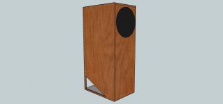
It's not a BIB, but most definitely inspired by my experiences with BIBs and also follows the basic BIB methodology of folding and general aspect ratio. Thought I'd post it here as well.
I just received two Fane FC-152F01TC fullrange drivers, rather nicely sized fullrange drivers. Due to their size, they reminded me of LC1A's, Tannoy Dual Concentrics etc. Made me think of big backloaded corner horns.
I have long wanted to build a pair of Olson exponential backloaded corner horns, but they won't fit our living room. I reverse engineered them from the plans, then took those parameters as a starting point for an offset driver parabolic pipe horn.
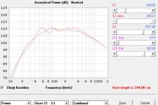
Throat is 430 cm² (as Olson corner horn), mouth is 1754 cm² (a little larger, due to the standard boards I use, insignificant effect in hornresp), length of the corner horn seems about 244 cm to me (centerline method), in my design it is 240 cm (or probably a bit longer). My design has the driver at 105 cm from the start of the pipe. This was really just chosen for convenience (my listening height) and fortunately works out in the sims.
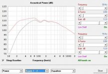
One sim shows my understanding of the Olson horn in red and my design in grey. What I sim as the Olson horn overlays pretty well with measured response of the real deal. The other sim is my design in grey and the effect of room gain in red. My big 12" BIB seems to get less room gain than earlier sealed box subwoofers, so I am curous whether it will really perform as designed.
Very curious about how it turns out.
It's not a BIB, but most definitely inspired by my experiences with BIBs and also follows the basic BIB methodology of folding and general aspect ratio. Thought I'd post it here as well.
I just received two Fane FC-152F01TC fullrange drivers, rather nicely sized fullrange drivers. Due to their size, they reminded me of LC1A's, Tannoy Dual Concentrics etc. Made me think of big backloaded corner horns.
I have long wanted to build a pair of Olson exponential backloaded corner horns, but they won't fit our living room. I reverse engineered them from the plans, then took those parameters as a starting point for an offset driver parabolic pipe horn.
Throat is 430 cm² (as Olson corner horn), mouth is 1754 cm² (a little larger, due to the standard boards I use, insignificant effect in hornresp), length of the corner horn seems about 244 cm to me (centerline method), in my design it is 240 cm (or probably a bit longer). My design has the driver at 105 cm from the start of the pipe. This was really just chosen for convenience (my listening height) and fortunately works out in the sims.
One sim shows my understanding of the Olson horn in red and my design in grey. What I sim as the Olson horn overlays pretty well with measured response of the real deal. The other sim is my design in grey and the effect of room gain in red. My big 12" BIB seems to get less room gain than earlier sealed box subwoofers, so I am curous whether it will really perform as designed.
Very curious about how it turns out.
Attachments

… Terry Cains Double-BEN?…
As close as you can get would be Sachiko or Kirishima. Vulcan is next up.
dave
- Home
- Loudspeakers
- Full Range
- Terry Cain's BIB -why does it work and does anyone have those Fostex Craft Handbooks?