Also Catalonian viewpoint!
Are you running for president?
I could certainly get it serviced elsewhere but the market value of the amp does not justify an expensive repair. Like an old car I'm going to fix it myself just for the shear fun of it. I've purchased an oscilloscope, fluke 177, dc power supplies etc – its going to be just in the 80s when I writing automatic test software for missile systems.If I were you, I would look at other dealers in Europe.
I see there is a dealer in the Hague, Italy, Serbia, Greece and even Turkey... I imagine at least one would be interested in acquiring your business.
If not maybe some clearer photographs of those diodes would help?
Does one channel still work? Any chance of posting some voltages off it?
As regards the state of the repair, both channels are damaged in the same way, all the constant current diodes are all dead but the zeners 43B,47B, 47B appear to be alive and well. I have not yet determined their breakdown voltage yet but its >20v as expected, I'm awaiting a variable dc power supply but currently I'm binding batteries together. I measured the output capacitors correctly they are 20uf as someone suggested.
Member
Joined 2009
Paid Member
I'm going to fix it myself just for the shear fun of it.
That's the spirit !
It really maybe as simple as replacing the current-source diodes and then checking it over t ensure everything is working properly.
The backside of the main pcb has evidence of a fair bit of solder flux (and the other pcb too) which would be worth cleaning up once you're finished. I assume the original manufacturer did those 'repairs' on the backside, the cut traces and fly-wires. Boy what a mess. Anyhow, it's proper industrial practice to secure fly-wires to the board at a couple of spots with some epoxy so that the solder joints themselves are not responsible for mechanical stability.
Member
Joined 2009
Paid Member
...The Zanden is a much better preamp than 99% of the so called high-end ... The "circuit" as drawn already speaks volumes.
What makes this a better preamp ?- I don't think I've seen a 'modern' unit deconstructed like this, what should I learn / take away from this one that I could learn ?
Mine has a single digit serial number, it was an ex-demo unit so I gather they were still fine tuning.That's the spirit !
It really maybe as simple as replacing the current-source diodes and then checking it over t ensure everything is working properly.
The backside of the main pcb has evidence of a fair bit of solder flux (and the other pcb too) which would be worth cleaning up once you're finished. I assume the original manufacturer did those 'repairs' on the backside, the cut traces and fly-wires. Boy what a mess. Anyhow, it's proper industrial practice to secure fly-wires to the board at a couple of spots with some epoxy so that the solder joints themselves are not responsible for mechanical stability.
That sounds reasonable. On the foil side, or by using a cotton tipped stick (Q-Tip here), you can use lacquer thinner on the flux. If there are no components on that side, lacquer thinner with an old toothbrush works wonders. Let it drip to one side and use a paper towel to blot up the residue. You can do this a couple times if the flux is especially heavy.
-Chris
-Chris
you can use lacquer thinner on the flux.
It's quite volatile, and smells, so best to do your cleaning outside if anyone in the house is bothered.
jeff
Are you running for president?
I'm the Molt Honorable President😉
zeners 43B,47B, 47B appear to be alive and well.
If you get the correct zener voltages and the raw dc voltage it will be easy to make a very educated guess about both current sources.
Why? Because of the fixed bias and because there is definitely no more than 10v drop across the plate load. The PS ccs is similarly limited: it has to supply the nominal current through the zeners which is known from the datasheet plus the current through the tube.
So here's an update, over the last 4 weeks I have sent various emails requests to Zanden (sales, technical, info) and yet to receive a reply of any form. Perhaps a sales enquiry would determine if the site is alive or dead. Anyone fancy requesting some info?
Anyway my variable voltage supply has arrived and I discovered the zener diodes breakdown values relate to their markings 43v, 47v 47v giving 137v. I played with the load resister and found breakdown occurred with as little as 0.7ma. So I'll try and match these characteristics against some datasheets to determine a working value for Iz. I'm just left with the difficult task of identify the constant current diodes.
Anyway my variable voltage supply has arrived and I discovered the zener diodes breakdown values relate to their markings 43v, 47v 47v giving 137v. I played with the load resister and found breakdown occurred with as little as 0.7ma. So I'll try and match these characteristics against some datasheets to determine a working value for Iz. I'm just left with the difficult task of identify the constant current diodes.
Analog_sa is right.
You could use a different current source circuit using currently available components that are both inexpensive and easily obtainable.
It looks like you even have space in the box to do all this, and still allow for putting it all back as it originally was...
To be honest, it might even perform better than the original. Nobody will be the wiser.
Hi jahsavage,
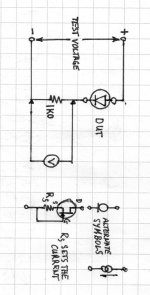
Just test each current diode, one at a time. Use something like an accurate 1K0 resistor to run the current through and measure the voltage drop, 1 V = 1 mA. This should be more accurate than your current function in your meter.
Most current diodes have a tolerance of 10%, 5% for the more accurate ones. Current diodes are difficult to damage unless too high a voltage is dropped across them. Most are rated for 50 VDC, the other range is 100 VDC devices. So for replacement you can opt for 100 VDC devices with a 5% tolerance.
The next option would be the Microchip DN2540N3 (TO-92 case). These are good for 400 VDC drop, so zero worries. They are D-Mosfets, so you can easily create a two terminal current source. I use them often enough that way. You can set your current up pretty accurately through these. You simply make a test setup that allows you to place a resistor in series with the source lead, the gate connects at the "bottom". You measure the current the same way as above and your new power supply becomes useful again. By adjusting the resistor value, you adjust the current that will flow. It really is that easy. I used a 1 K pot and simply adjusted to the right current, then used a resistor to get the same value of current. You can put resistors in parallel to get a closer value if you feel better about it. Once set these are very stable. I happen to use surface mount resistors mounted directly on the component leads. Works like a charm.
So, step #1. Measure the current with the existing diodes. If you test backwards, they will conduct like a diode, so ramp up your power supply while watching the voltage drop across the 1K0 resistor. Don't turn it up too high.
These diodes were available with currents ranging from 0.1 mA up to 20 mA or so. I would expect yours to run above 1 mA and probably lower than 10 mA. They used two in parallel to increase the current while keeping the temperature in the diodes low to keep the temperature lower than what would create too much heat in the diodes.
If you need, someone can draw this out for you. I can tomorrow if you let us know.
-Chris
Further speculation
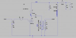
OK, one thing is clear: this design works close to the edge, which probably explains why it failed.
We are still missing the value of the raw dc voltage but this is not so critical for analysis.
The issue comes from the relatively high B+ and the limited maximum voltage of the current diodes. These seem to be limited to either 100v or 50v depending on nominal current.
Looking first at the plate loads, a sensible value for the op point seems to be 10mA which can easily be obtained from 2 parallel 4.7mA current diodes (1N5314). The tube will then operate at -3.6v, 9.4mA, 91v.
The CRDs for the shunt regulator are more problematic because they need to provide a sufficient current through the zeners. I think 5mA is an absolute minimum but this will depend upon the particular chosen device. Problem is that above 4.7mA i have been unable to locate any axial devices that could withstand a 100v; these appear to be limited to either 30v or 50v (Semitec).
So, the raw dc supply should not exceed 137v by much. 160-170v seems to be a safe limit. It cannot also be too close to 137v as a 10% mains fluctuation could render the raw dc below the zener regulation.
It is easy to see how the unit failed. If the plate voltage gets applied by connecting the umbilical of the powered external PS there will be a brief but deadly instant in which the decoupling 22uF will apply the entire raw voltage across the CRDs of the shunt regulator. If these fail by shorting they will bring zeners and other crds with them.
So, safe operation relies on the slow ramping of the tube rectifier output.
Attachments
Hi analog_sa,
You are correct. I completely agree with your failure analysis.
Hi jahsavage,
In order to upgrade this preamp, I would recommend using the DN2540N5, which is a TO-220 package and can have a heat sink attached. The 400 VDC breakdown and the few watts of dissipation would probably cut the needed devices down to one per channel while also making it a reliable design. I'm surprised that there aren't zener diodes across the current diodes for protection to keep the diodes from shorting.
I can draw the test circuit larger in case you need. Does this give you enough information to test your own D-Mosfets (DN2540N5)?
Best, Chris
Attachments
Chris,
Nothing against the depletion mode fets, those are pretty much bullet proof in this position, even the TO92, only:
- such a dramatic modification will have a disastrous effect on resale value, even if executed in a professional manner (add on pcbs)
- it will certainly affect sonics in some way, not necessarily bad, but it will not play like stock anymore
I have to admit i am really surprised that you in particular would think this is a good idea.
Hi analog_sa,
Well, in this case I don't see much in the way of options. The current diodes are getting more difficult to find, and they aren't cheap either. Once equipment fails due to a design issue, I think its time to correct the problem. After all, the equipment owner just wants to use his equipment. If resale is the goal, then by all means, repair as it was originally.
I often replace current diodes with either an LND150N3 or DN2540N3 or N5. But that is if the current diode has failed and the voltages are close to its maximum rating. I do this by installing the new components in the same location the current diode was in. To revert to the original design, one merely has to remove my parts and install the original part.
Now, replacing a resistor with a current diode, or one of the Jfet or D-Mosfet parts will most definitely change the performance of the equipment. Done right, the difference is an improvement in performance and sound quality.
Getting back to this situation, you yourself noted that the current diode is running very close to it's maximum spec. It is likely that the safety tolerance built into these parts is the only reason why there aren't a ton of these preamps sidelined for service. It would seem prudent to correct this situation by using a part that has a much higher breakdown voltage. Personally, I don't feel that replacing the current diode with these transistors without modifying the PCB wouldn't have any effect on it's resale value and may even make it much easier to sell.
Best, Chris
Well, in this case I don't see much in the way of options. The current diodes are getting more difficult to find, and they aren't cheap either. Once equipment fails due to a design issue, I think its time to correct the problem. After all, the equipment owner just wants to use his equipment. If resale is the goal, then by all means, repair as it was originally.
I often replace current diodes with either an LND150N3 or DN2540N3 or N5. But that is if the current diode has failed and the voltages are close to its maximum rating. I do this by installing the new components in the same location the current diode was in. To revert to the original design, one merely has to remove my parts and install the original part.
When replacing a current diode with the N-Jfet or N-Mosfet, I have not detected any changes in performance at all. They are the same basic thing. A current diode is just a Jfet with it's gate shorted to the source in the package, so there won't be any performance difference as the replacement is essentially what is in there in the first place.- it will certainly affect sonics in some way, not necessarily bad, but it will not play like stock anymore
Now, replacing a resistor with a current diode, or one of the Jfet or D-Mosfet parts will most definitely change the performance of the equipment. Done right, the difference is an improvement in performance and sound quality.
Getting back to this situation, you yourself noted that the current diode is running very close to it's maximum spec. It is likely that the safety tolerance built into these parts is the only reason why there aren't a ton of these preamps sidelined for service. It would seem prudent to correct this situation by using a part that has a much higher breakdown voltage. Personally, I don't feel that replacing the current diode with these transistors without modifying the PCB wouldn't have any effect on it's resale value and may even make it much easier to sell.
Have I addressed your concern? I'm after the best repair for the owner of this equipment without changing the sound quality, which this "modification" will do. The sound quality is maintained at its original factory character. I would be very surprised if this affected the sound quality in any way.I have to admit i am really surprised that you in particular would think this is a good idea.
Best, Chris
Put it this way - some listeners, myself included, have found a substantial audible difference between various depletion mosfets used as a CCS: DN2540, LND150, IXTP01N100D. And of course they are all different to a jfet set for the same current.
I think with "Audiophile" equipment, making any electronic changes that would improve performance would substantially reduce the value of the unit as it is no longer original. It is the original design that garnered the value.
This is why this preamp schematic is a great DIY candidate.
Analog_SA's repair parts could be installed as original.
these diodes rated current value can be +-15% different, so you may want to buy 10 ( $25ea. ) and match them as closely as possible for the diodes feeding the tube.
The diodes feeding the zener stack won't need to be matched.
Last edited:
The 'statistical' regulator in Morgan Jones' book is worth looking at as an option to make a more lasting 'repair' imho.
Of course, I would not use a stack of 5.6v zeners as Morgan did. The improvement in sound quality might ruin its unique 'character' (?)
Stocktrader - right now it does not work. This is the biggest problem to audiophool 'resale value' if that is the goal.
Of course, I would not use a stack of 5.6v zeners as Morgan did. The improvement in sound quality might ruin its unique 'character' (?)
Stocktrader - right now it does not work. This is the biggest problem to audiophool 'resale value' if that is the goal.
Last edited:
This is the surreal world of high end audio, would any potential purchaser even know?I think with "Audiophile" equipment, making any electronic changes that would improve performance would substantially reduce the value of the unit as it is no longer original. It is the original design that garnered the value.
This is why this preamp schematic is a great DIY candidate.
Analog_SA's repair parts could be installed as original.
- Home
- Amplifiers
- Tubes / Valves
- Repairing Hi-End Preamplifier