The distortion in the speaker's acoustic output may be improved or reduced by adding resistance; that depends on exactly what effects are causing the acoustic nonlinearity and how they correlate with impedance nonlinearity. However, you were not measuring acoustic distortion but current distortion. The cable resistance was merely the current sense resistor - this is the point which some people seem unable to grasp, wedded as they are to the tired and unphysical idea that speaker cables are a source of distortion themselves.vzaichenko said:Assuming the amplifier's Zout is low enough, it also improves the speaker's damping and reduces the voltage fluctuations, caused by the speaker's impedance non-linearities (the speaker is driven "harder" with a better cable).
As a result, I expect the total distortion, produced by the speaker with a lower-impedance cable, to be lower than the total distortion, produced by the speaker with a higher-impedance cable.
Extrapolating from resistor nonlinearity to cable nonlinearity (on the spurious ground of extra length) is poor engineering, presumably based on poor understanding.xrk971 said:That’s a single 2cm long part. It doesn’t surprise me that a 2m long multi stranded cable with insulation might have something non-linear going on.
If cables distort then your measuring cables distort too, so you cannot rely on any measurement.
This thread is getting increasingly silly. It appears that many contributors are confused by the physics and maths of a simple potential divider.
I am confident that all here will agree that there is an effect. However, it is not nonlinearities in the cable that are causing the change, it is the cable's impedance which is changing the outcome. With no cables, the amp has the best chance of fighting the non linearities, a resistive cable makes it less possible for the amp to do so. Think of it like a spring...a slinky suspending a golf ball vs a garage door spring. The slinky has less control of where the load goes..yet, both are still linear within the range of operation. (granted, this analogy falls apart terribly fast as springs are typically linear over a range of extensions then become highly non linear prior to plastic deformation).I was the one who stumbled upon the higher distortion FFTs and alerted Valery to it. I think his data clearly shows that there are effects of the speaker cable on the FFT. It’s not the same as no cable for sure. Whether or not one wants to believe that the cable is the cause of the changes is something that is being argued ad infinitum here.
If you have a sound interface, connect it to your dummy load with and without cable. See what you get. Yes, take all proper precautions to ground properly. You will still see distortion. It’s not the cable that makes the distortion visible - imagine a very short 5cm cable. It won’t be the same as long cable - it will be close to same as no cable. The effect is caused by the cable not that the cable makes it easier to see.
I have seen distortion in an amp change via simple substitution of one brand of thin film resistor vs another (Vishay vs Panasonic) in the feedback or output device source resistor, and I get different harmonic profiles (relative H3 was higher va H2 on one and vice versa). That’s a single 2cm long part. It doesn’t surprise me that a 2m long multi stranded cable with insulation might have something non-linear going on.
As to your resistors, it is important to understand the physical processes involved in making the resistors, the materials of the resistor, the material resistance characteristics, as well as the environment the resistor is placed into.
Such things as voltage dependent resistance, how it's trimmed (if any), endcap (termination) materials...so many things..
Sometimes, the simple substitution is not quite as simple as suspected. Trust me, I've banged my head against that wall many a time..😱
Jn
Maybe resistor brand change analogy was not good. Regarding resistor endcap termination, maybe that might be similar to how the speaker cables are terminated (opening up yet another can of worms). Soldered, soldered to banana jack, crimped to banana jack, Speakons, bare wire screwed down with binding post clamp, etc. I agree that the effect of a loose spring vs a stiff spring really influences how the load at the end can be driven.
Maybe resistor brand change analogy was not good. Regarding resistor endcap termination, maybe that might be similar to how the speaker cables are terminated (opening up yet another can of worms). Soldered, soldered to banana jack, crimped to banana jack, Speakons, bare wire screwed down with binding post clamp, etc. I agree that the effect of a loose spring vs a stiff spring really influences how the load at the end can be driven.
If this is true, the effect is negligible and orders of magnitude lower than the coils (in serie with bass and parallel too), output transistors resistors components in series, as well as the inductors of the transducer which has all 1000x more resistance than the 0.05R 3 meter wire.
A lose connections on the other hand will cause distortion in high frequency. I doubt the makers of electrical components leave microscopic gaps to smear the high frequencies.
It's the changes in the resistance of the cables that causes the changes in the measurements. I don't think that's a matter of belief or that there's anything to argue about, unless you meant something else.Whether or not one wants to believe that the cable is the cause of the changes is something that is being argued ad infinitum here.
Probably "minimise" is not a good word in my statement - something like "reduce" would be better. However, my thinking is - a low-impedance cable does not only make the speaker's impedance non-linearity less visible.
Assuming the amplifier's Zout is low enough, it also improves the speaker's damping and reduces the voltage fluctuations, caused by the speaker's impedance non-linearities (the speaker is driven "harder" with a better cable).
As a result, I expect the total distortion, produced by the speaker with a lower-impedance cable, to be lower than the total distortion, produced by the speaker with a higher-impedance cable.
What do you think?
Some measurements with a microphone might be the only way to really see the true end result of cabling changes.
You really like to beat the dead horses here, again and again and again.
Add feedback to the story to spice it up. 😀
Add feedback to the story to spice it up. 😀
Last edited:
Some measurements with a microphone might be the only way to really see the true end result of cabling changes.
Both Wesayso and myself have come across the odd mic measurement of a speaker where a cable caused the phase of the to show some changes. In my case, it was the proximity with another cable - a mains power cord. Made me scratch my head though how it can show up as an acoustic measurement from the speaker.
And multiple output transistors sound like a chorus I'll have you know 🙄You really like to beat the dead horses here, again and again and again.
Add feedback to the story to spice it up. 😀
I knew this would degenerate into the usual cable thread. And I can't believe DF96 is still banging his head on this wall.
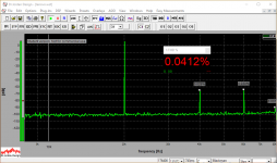
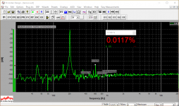
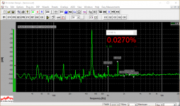
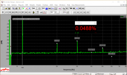
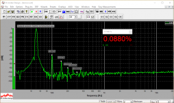
Current in 3m cable with 8R dummy load
OK, here are some more spectrums - measured across the cable wire.
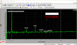
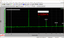
This set if for the dummy load at the end of the shorter cable.
OK, here are some more spectrums - measured across the cable wire.
This set if for the dummy load at the end of the shorter cable.
Attachments

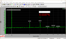

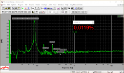

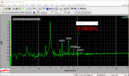
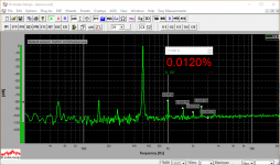
Current in 3m cable with the speaker
Now - short cable with the speaker.
Now - short cable with the speaker.
Attachments
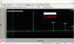
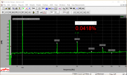

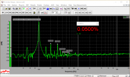


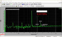
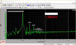
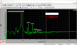
Current in 12m cable with the speaker
Finally - longer cable with the speaker.
Finally - longer cable with the speaker.
Attachments


Some measurements with a microphone might be the only way to really see the true end result of cabling changes.
Jeff, I'm thinking about this kind of test - I've got a Behringer C3 studio condenser microphone, need to bring it from the other office along with the microphone amplifier. Then we can run a rather clean experiment.
Speaker impedance non-linearity seems to be noticeably higher below 200Hz with the longer cable.
Parallel wires carrying current attract. This combined with the compliance characteristic of typical insulations would allow mechanical resonance, with mechanical losses of the insulation determining the Q. Has anybody swept speaker cables to determine the nature of this electromechanical resonance?
Dan.
Dan.
- Status
- Not open for further replies.
- Home
- Amplifiers
- Solid State
- Speaker cables don't influence harmonic distortion!