@alex mm
OK. I can give you my personal email. 🙂
@junior35
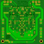
Bottom of PCB. 🙂
I think junior meant bottom copper layer in B/W in pdf format for etching.

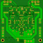

I think junior meant bottom copper layer in B/W in pdf format for etching.
Thank you for clarifying
Technical specifications of SX9
Can you please post the technicla details such as:
Max power/input impedance/THD/IMD/ slew rate etc. ?
Thanks and regards,
Sumesh
Can you please post the technicla details such as:
Max power/input impedance/THD/IMD/ slew rate etc. ?
Thanks and regards,
Sumesh
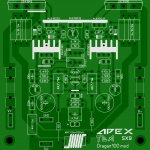
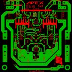
A new version of APEX SX9.
Thanks to Dragan100!
Is it really good idea to put the output coil so close to the input connector?
Sajti
Is it really good idea to put the output coil so close to the input connector?
Sajti
Opps very bad idea
the output bobbin must be away from the input connector.
Can you please post the technicla details such as:
Max power/input impedance/THD/IMD/ slew rate etc. ?
Thanks and regards,
Sumesh
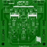
New version:
THD 0,05%@1Wrms@8R0@1KHz
THD @100Wrms@8R0@1KHz = cca 0,1%, PSU +/-45VDC
SlewRate cca 50V/usec
Bandwith 2Hz-520KHz (-3dB)
SNR cca 106dB
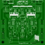
Final version.
Shouldn't the drivers be on the main heatsink?
Your PCB also has different components than Mr. Apex's schematic. Did you make modifications to it? If so then it would be a good idea to post the updated schematic as well.
NoShouldn't the drivers be on the main heatsink?
There is 2 versions of AX9.Your PCB also has different components than Mr. Apex's schematic. Did you make modifications to it? If so then it would be a good idea to post the updated schematic as well.
First schematic in post #10156,PCB #10167http://www.diyaudio.com/forums/solid-state/164093-100w-ultimate-fidelity-amplifier-post5374014.htmlhttp://www.diyaudio.com/forums/solid-state/164093-100w-ultimate-fidelity-amplifier-post5373747.html
and second (Dragan100 mod) schematic in post #10183,PCB #10191.
Hi to all
today finished my work Ax14
can you tell me if I set the correct bias?
measured on the resistance of 0.22 ohm, 15mV
today finished my work Ax14
can you tell me if I set the correct bias?
measured on the resistance of 0.22 ohm, 15mV
An externally hosted image should be here but it was not working when we last tested it.
Hi to all
today finished my work Ax14
can you tell me if I set the correct bias?
measured on the resistance of 0.22 ohm, 15mV
An externally hosted image should be here but it was not working when we last tested it.
Attachments

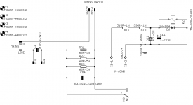
Mr. Mile,
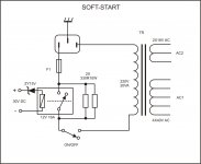
Can this super simple softstart work for your high power amps? Like BX-22 and SR 200 etc?
Very few components.
Ckt is from TI app note
http://www.ti.com/lit/an/snaa057b/snaa057b.pdf
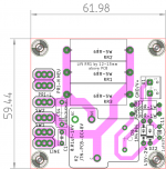
Layout has 100mil cl for high voltage traces.
regards
Prasi
Can this super simple softstart work for your high power amps? Like BX-22 and SR 200 etc?
Very few components.
Ckt is from TI app note
http://www.ti.com/lit/an/snaa057b/snaa057b.pdf
Layout has 100mil cl for high voltage traces.
regards
Prasi
Attachments
Last edited:
Mr. Mile,
Can this super simple softstart work for your high power amps? Like BX-22 and SR 200 etc?
Very few components.
Ckt is from TI app note
http://www.ti.com/lit/an/snaa057b/snaa057b.pdf
Layout has 100mil cl for high voltage traces.
regards
Prasi
Yes, but there is simplier soft start circuit from B500 thread. Use zener diode instead resistor for sharp switch.
Attachments
Last edited:
Yes, but there is simplier soft start circuit from B500 thread. Use zener diode instead resistor for sharp switch.
Its indeed simpler!😀
Thanks Mr. Mile.
regards
Prasi
- Home
- Amplifiers
- Solid State
- 100W Ultimate Fidelity Amplifier