If you
can drive 500 ohms without significant distortion, you are doing fine.
Excellent, here are my results at 500 ohms

They are cute little guys

For maximum bandwidth you want buffers that have output impedances
lower than the DC values of the primaries. For the Jensen and Cinemag
examples, 25 ohm is desirable, although things don't fall apart until quite
a bit higher.
I need to think of a good way to test this on my bench.
I used to do quick and dirty method that would probably get you there. When you load the output with a value equal to the source Z, the output level will be cut in half(-6db). At 10k load, a 25 ohm output Z is relatively meaningless. But with 25 ohm load, 1/2 your voltage is dropped in the output Z and 1/2 on the load 
There is a nominal impedance for the transformer primaries, but that's for when
the secondaries are driving their rated impedance, which in these instances
they usually aren't.
With the 150:150:150:150 ohm line transformers we've been using as
autoformers, I have measured mid-band impedances of 5K or so. If you
can drive 500 ohms without significant distortion, you are doing fine.
For maximum bandwidth you want buffers that have output impedances
lower than the DC values of the primaries. For the Jensen and Cinemag
examples, 25 ohm is desirable, although things don't fall apart until quite
a bit higher.
So, plugged them in and generated some smoke 🙁
In thinking about it, I have a few questions. Here is the schematic that elicited the smoke, I was using a balanced to SE XLR Adapter

1.) I am switching the buffer in and out of the circuit via a relay. I am just moving the input of the buffer, the output stays connected. Will this work? Is it better to switch the output, or must I switch both the input and out of the buffer?
2.) My buffer saw as load the primaries in parallel, which is pretty low and caused a resistor to smoke. This is much lower than the 500R above. This is because the negative input was connected to ground via the adapter. I am doing something wrong here, obviously. How can I fix it?
Thanks!
Yes, you are doing something wrong.
The first step on the path to enlightenment.
I don't think you want the output of the buffer and the input signal
connected to the transformer at the same time. Also, always see to it
that the buffer input has something to look at, even if it's only a large
value resistor to ground.
The first step on the path to enlightenment.
I don't think you want the output of the buffer and the input signal
connected to the transformer at the same time. Also, always see to it
that the buffer input has something to look at, even if it's only a large
value resistor to ground.
Yes, you are doing something wrong
The smoke was the first indication of that 🙂
Ok, so switch the output of the buffer. Makes sense!
It seems that I should also switch the input. Take this example:

I seem to loose the benefit of a balanced input, as I have the input resistor to ground? So, I guess if I wanted to have the buffer flexibility, I need switch it completely in/out, meaning both input and output?
In the case of the first diagram, where the switch toggles the buffer to be in-line, doesn’t the buffer still see 25R in parallel with 25R as load?
You want the buffer to always have some DC connection to ground,
even if it's 1 Meg (or more likely 100K). Otherwise it might be led astray...
even if it's 1 Meg (or more likely 100K). Otherwise it might be led astray...
You want the buffer to always have some DC connection to ground,
even if it's 1 Meg (or more likely 100K). Otherwise it might be led astray...
Thank you!
... and the second part of my question I believe is answered by “yes, the buffer has to drive a DC load of 25 in parallel with 25, as the primaries are in parallel.” My little buffer can’t do this.
I think the original question I meant to ask, was “when I am testing my buffer for low distortion, how can I approximate the load and/or use the transformer itself as an load approximation”. I misunderstood your answer of “500” to mean, stick a 500 ohm resistor on the output.
So, given my confusion, what would be the best way to bench test the buffer at a good approximately of the transformer load? Just use the transformer itself with the secondaries open?
Obviously the best way is to test it into the actual intended load.
That said, I find that a buffer capable of driving the "rated" impedance as a
resistance will do well enough into the transformer.
For example, the Jfet buffers I use won't drive 150 ohms, but are ok
into a 150 ohm tap on a transformer as long as the secondary system is
not driving its rated impedance.
I have a couple of amplifiers with 150:150:150:150 coils as autoformers
giving a gain of 12 dB into 10K ohm. They work fine driven by a pair of
2SK170/2SJ74.
Hi Dear Mr. Pass, Since I built a sort of CSX1 but with balanced couple of Vfets and I am very comfortable with the dynamic of this topology with my speakers, I am interested in those transformers, where is possible to get them? Thanks in advance.
Best Regards
Best Regards
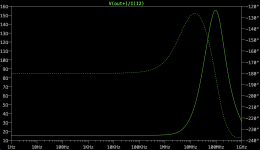
ok, so I've measured the output impedance to be quite low, in fact it matches my simulation.

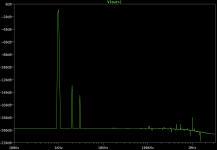
In terms of the simulation, the FFT looks similar in relative magnitude, but the values are lower in the (perfect) sim. Compare to the measured FFT above.

In terms of the resistor to ground, I'm using a diamond buffer topology and my input devices are half of a PHPT610030NPK. Here's the datasheet:
http://www.mouser.com/ds/2/302/PHPT610030NPK-534221.pdf
I've tried 100K to ground and 1M to ground. I don't see much of any difference with the distortion on the output. What should I be looking for when choosing this resistor?
In terms of the simulation, the FFT looks similar in relative magnitude, but the values are lower in the (perfect) sim. Compare to the measured FFT above.
In terms of the resistor to ground, I'm using a diamond buffer topology and my input devices are half of a PHPT610030NPK. Here's the datasheet:
http://www.mouser.com/ds/2/302/PHPT610030NPK-534221.pdf
I've tried 100K to ground and 1M to ground. I don't see much of any difference with the distortion on the output. What should I be looking for when choosing this resistor?
Attachments
Hi Dear Mr. Pass, Since I built a sort of CSX1 but with balanced couple of Vfets and I am very comfortable with the dynamic of this topology with my speakers, I am interested in those transformers, where is possible to get them? Thanks in advance.
Best Regards
Both Jensen and Cinemag have several offerings fitting this description.
Jensen JT-123-FLPCH
Cinemag CMOQ-4LPC

Hello all!
How many pairs of Sony devices that be driven by the transformer in the CSX2 circuit? How does this parallelization change the output impedance and damping factor?
How many pairs of Sony devices that be driven by the transformer in the CSX2 circuit? How does this parallelization change the output impedance and damping factor?
One more question, what’s magic about 24V? Can I reduce this to get things to work with a 31.5V raw supply (2x22VAC as opposed to 2x24VAC), by reducing the 3 x 9.1V zener stack a bit (edit: or change R1?)
Last edited:
I would consider the DC voltage under load and line variations. Conceivably
you may find the DC too close to the voltage of the zener stack.
you may find the DC too close to the voltage of the zener stack.
- Status
- Not open for further replies.
- Home
- Amplifiers
- Pass Labs
- Article - Sony VFETs part 1