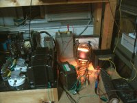
I have some very large tubes I got years ago from a radio transmission tower, which I purchased from them, but have no idea what I can use them for ... does anyone have any idea?? (see photos)
...I have a few of them, and another really large one --- just thought to get them at the time for possible use later on...
...I have a few of them, and another really large one --- just thought to get them at the time for possible use later on...
Attachments
Last edited:
Very nice, are they stealth tubes?
...'phantom tubes' ... LOL ...I have the photos up now...and might take some more
Last edited:
They sell these tubes to you why they were near end life.I have some very large tubes I got years ago from a radio transmission tower, which I purchased from them, but have no idea what I can use them for ... does anyone have any idea?? (see photos)
...I have a few of them, and another really large one --- just thought to get them at the time for possible use later on...
You can use these tubes to TX radio waves if you have all the auxiliary equips.
Its only they are suited.
Not that I know anything about it from personal experience but looking around . . . . .
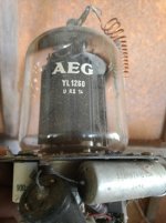
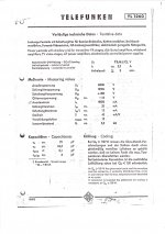
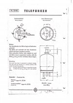
The Telefunken data sheet refers to the YL1260 as a "steep power pentode with shadow grille in hard glass technology."
For transmitter output stages, chain amplifiers, broadband amplifiers, television video stages."
It has a shadow grid for low partition noise (explained here) and also looks like it can use a lowish Vp (for a transmitter) with higher current capability than audio builders usually see. If there's a linear operating zone there somewhere it might make a nice power output. I'd be happy to have a few in a box somewhere.
Couple of links for you. One and Two
Indirectly Heated with 12.6 and only a 2.3 amp draw I wouldn't put it out of my stash without lighting it up first. The second data sheet calls it a high slope power tube and gives a spread of operating values that might be worth looking at. The shadow grid which is apparently usually internally connected on such types appears to have an external connection on this one.
Maybe ask Smoking-amp or Tubelab et al. for ideas for running it.
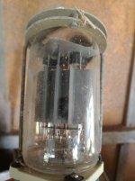
The second picture is 13E1. You can certainly build an amp with those. Morgan Jones Chrystal Palace amplifier in his book Valve Amplifiers is one.
Also Patrick Turner did a few SE designs:
monobloc-se32-13e1-cfb-2012version
Mind you the one you pictured looks pretty toasted.
Cheers
Matt
Also Patrick Turner did a few SE designs:
monobloc-se32-13e1-cfb-2012version
Mind you the one you pictured looks pretty toasted.
Cheers
Matt
YL1260
Too bad the datasheet doesn't give any curves!
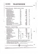
1500V max B+. Pdiss 250 Watt abs. max. Grid 2 400V, 15W abs. max. Looks like the shadow grid is max spec'd for -100V to +100V in operation. But grid 1 is only spec'd for -50V to +2V. Cathode 800 mA DC abs. max.
Typical operation:
B=+ = +600V, +225V for grid2, shadow grid +30V, grid1 bias -17V, cathode current 400 mA, internal Mu 13, Ri 5500 Ohms, Rload 500 Ohms
Surprising that the schadow grid is allowed to be positive. Grid1 gm is really high at 45 mA/V at 400 mA (frame grid maybe?). So this tube doesn't need positive grid 1 voltage like most power RF tubes.
-----------------------------------------------------
Seems a little bit, but clearly not exactly, like the 4D32 tube (which uses + grid1).
A "tiny" 7 pin "shadow grid" beam hexode tube: 6GU5
http://tubedata.milbert.com/sheets/049/6/6GU5.pdf
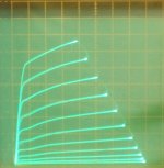
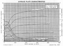
Curves below for the 6GU5 tube (2 mA/div Vert., 50V/div Horiz., 2V steps grid 1, +159V on grid2. (shadow grid is attached to cathode)
Second and third curve sets below are similar, but standard 6CB6 and 6EW6 tubes. Note how square the knees are.
I'm not real impressed with how square the plate curve knees are for the 6GU5. The shadow grid should be
-removing- the screen grid current effects!
(it's also a remote cutoff grid1 tube) Well, this is -no- YL-1260 for sure.
Some "guided grid" partial grid shielded triodes: 6FY5, 6FQ5, 6GK5, 6HK5
(all remote or semi-remote cutoff)
I'll bet George (Tubelab) would like a case of new YL-1260s!
Too bad the datasheet doesn't give any curves!
1500V max B+. Pdiss 250 Watt abs. max. Grid 2 400V, 15W abs. max. Looks like the shadow grid is max spec'd for -100V to +100V in operation. But grid 1 is only spec'd for -50V to +2V. Cathode 800 mA DC abs. max.
Typical operation:
B=+ = +600V, +225V for grid2, shadow grid +30V, grid1 bias -17V, cathode current 400 mA, internal Mu 13, Ri 5500 Ohms, Rload 500 Ohms
Surprising that the schadow grid is allowed to be positive. Grid1 gm is really high at 45 mA/V at 400 mA (frame grid maybe?). So this tube doesn't need positive grid 1 voltage like most power RF tubes.
-----------------------------------------------------
Seems a little bit, but clearly not exactly, like the 4D32 tube (which uses + grid1).
A "tiny" 7 pin "shadow grid" beam hexode tube: 6GU5
http://tubedata.milbert.com/sheets/049/6/6GU5.pdf
Curves below for the 6GU5 tube (2 mA/div Vert., 50V/div Horiz., 2V steps grid 1, +159V on grid2. (shadow grid is attached to cathode)
Second and third curve sets below are similar, but standard 6CB6 and 6EW6 tubes. Note how square the knees are.
I'm not real impressed with how square the plate curve knees are for the 6GU5. The shadow grid should be
-removing- the screen grid current effects!
(it's also a remote cutoff grid1 tube) Well, this is -no- YL-1260 for sure.
Some "guided grid" partial grid shielded triodes: 6FY5, 6FQ5, 6GK5, 6HK5
(all remote or semi-remote cutoff)
I'll bet George (Tubelab) would like a case of new YL-1260s!
Attachments
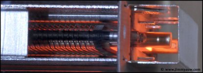
Here are some YL1260 close-up pics at this link:
http://jimmyauw.com/wp-content/uploads/2014/02/TelefunkenYL1260_2.jpg
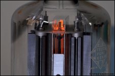
Looks like it has some large grid1 support posts, so it is most likely a frame grid1. (you can also see the frame support straps in the photo below) (and now we know why the grid 1 is only allowed to go +2V! or else Poof!! ) Looks like graphite anodes too. Very nice construction. Since the screen grid is not a frame grid, they used a wire pitched "shadow grid" in front of the screen grid, with equal wire pitch, to ward off screen current.
Unfortunately still no plate curves available. Would be interesting to see how a well designed shadow grid works to avoid screen current.
---------------------------------------------------------------------
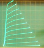
Of some interest would be the E130L, which uses matched/aligned frame grids for both grid 1 and grid 2. Very square knee curves (pics 2 and 3 below).
Then there are 12HL7, 12HG7, 12GN7 with a frame grid1, but an ordinary wire grid 2. No grid wire alignment possible to avoid screen current. But they -still- have fairly square knee curves, miraculously.
So does the YL1260 really -need- a shadow grid? Some curves please....
pics:
YL1260 close-up
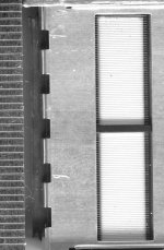
E130L aligned grids (millimeter scale on left)
E130L plate curves
12HL7 curves
12HL7 in Twin/Crazy drive
YL1260 grids, closer up
http://jimmyauw.com/wp-content/uploads/2014/02/TelefunkenYL1260_2.jpg
Looks like it has some large grid1 support posts, so it is most likely a frame grid1. (you can also see the frame support straps in the photo below) (and now we know why the grid 1 is only allowed to go +2V! or else Poof!! ) Looks like graphite anodes too. Very nice construction. Since the screen grid is not a frame grid, they used a wire pitched "shadow grid" in front of the screen grid, with equal wire pitch, to ward off screen current.
Unfortunately still no plate curves available. Would be interesting to see how a well designed shadow grid works to avoid screen current.
---------------------------------------------------------------------
Of some interest would be the E130L, which uses matched/aligned frame grids for both grid 1 and grid 2. Very square knee curves (pics 2 and 3 below).
Then there are 12HL7, 12HG7, 12GN7 with a frame grid1, but an ordinary wire grid 2. No grid wire alignment possible to avoid screen current. But they -still- have fairly square knee curves, miraculously.
So does the YL1260 really -need- a shadow grid? Some curves please....
pics:
YL1260 close-up
E130L aligned grids (millimeter scale on left)
E130L plate curves
12HL7 curves
12HL7 in Twin/Crazy drive
YL1260 grids, closer up
Attachments
Last edited:
ri of 500 ohms, so in SE, about 1500 ohms anode load...
plate dissipation of 250 watts means forced air cooling but running it 180 watts gives you 45 watts output...
Vp of 500 volts and cathode current of 360 mA, wow...
the thing that bogs me is the grid leak need to be low resistance,meaning transformer coupled...low impedance drive is a must...
45ma/v of transconductance means liable to runaway bias...
i wish i can get my hands on such tubes....
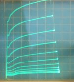
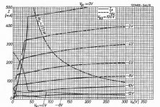
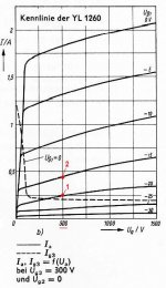
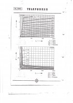
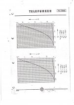
Plate curves YL1260 here:
YL 1260, Tube YL1260; Rohre YL 1260 ID20456, HEXODE
YL 1260, Tube YL1260; Rohre YL 1260 ID20456, HEXODE
Thank you so much Sorento!
(duh, I didn't scroll down to see the curves earlier )
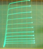
Very nice curves too. Screen current effects are just plain -gone-
So shadow grids work wonderfully!
Imagine this tube for ultralinear (UL) mode!
I think the race is on to find the last 3 of these tubes on the planet...
(duh, I didn't scroll down to see the curves earlier
)Very nice curves too. Screen current effects are just plain -gone-
So shadow grids work wonderfully!
Imagine this tube for ultralinear (UL) mode!
I think the race is on to find the last 3 of these tubes on the planet...
Last edited:
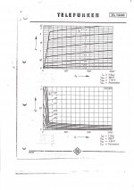
Hmmm, here are a couple more "shadow grid" tubes, and their curves are just -awful-.
6FG5 looks like a tetrode! Well, 6FS5 is not quite so bad. Both are remote cutoff junk.
What goes on here? Why bother with a shadow grid to get this crud?
Maybe there is something to that +30V on the shadow grid for the YL1260.
http://tubedata.milbert.com/sheets/093/6/6FG5.pdf
http://tubedata.milbert.com/sheets/093/6/6FS5.pdf
Attachments

Last edited:
What goes on here? Why bother with a shadow grid to get this crud?
Does the Philips explanation help answer that?
Attachments
Would make a hell of a Fender Champ.
The dates are wrong!
Correct:Ug2=+225V,Ug3=+30v
Would make a hell of a Fender Champ.
Can you make a big Fender Champ with a tube and power supply from a radio broadcast station? Yes.
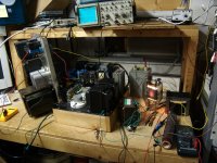
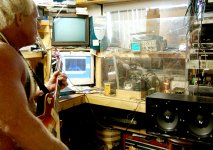
Recipe: Take an 833A tube (commonly used in Gates and RCA AM radio broadcast transmitters in the 1950's). Power it with a 1500 volt 1/2 amp supply lifted from a Motorola VHF base station for fire / police use. Drive it with the circuitry in one of my 845SE HiFi amps. Feed the HiFi amp with an ADA MP-1 MIDI guitar preamp. Connect some speakers and blast the world with 200 watts of single ended screaming guitar sound.
Bias was set at 275 mA and the tube sockets was carefully crafted from Vise Grips and hose clamps. For actual use I had a 1/4 inch thick sheet of Lexan polycarbonate plastic between me and it, and a fire extinguisher ready!
Attachments
RE: Hearinspace
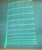
The "shadow grid" scheme is intended to lower noise by removing most partition noise from screen current. I see that. But the 6FG5 has got a BIG bump of screen current at low plate voltage, subtracting out a HUGE slug of plate current to make it look like a tetrode.
OK, maybe -above- the "tetrode" wart, the 6FG5 tube could be low noise. Just not what I expected. The YL1260 appears very able to remove the total "screen" current everywhere. Seems like the 6FG5 has got it's "shadow" focusing out of focus. Maybe it needs +30V on the shadow grid.
-----------------------
RE: George
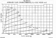
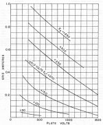
I hope you didn't give away any YL1260s when you cleaned up the shop (warehouse). That 833A looks impressive for power output, but with -Amperes- of grid 1 current, it probably is not qualifying for low noise adjacent radio band silence. The 833A Triode, with positive grid, does get the sharp "knees" right though. (then again, at 220 mA "screen" current, looks like the YL1260 shadow grid is "just" making for a 2 to 1 improvement, relative to plate current, versus the 833A)
pics:
1) 833A plate curves
2) 833A grid current curves
3) YL1260 plate curves (courtesy of Wolfgang Holtmann at: YL 1260, Tube YL1260; Rohre YL 1260 ID20456, HEXODE )
4) 6FG5 "ugly" plate curves
Does the Philips explanation help answer that?
The "shadow grid" scheme is intended to lower noise by removing most partition noise from screen current. I see that. But the 6FG5 has got a BIG bump of screen current at low plate voltage, subtracting out a HUGE slug of plate current to make it look like a tetrode.
OK, maybe -above- the "tetrode" wart, the 6FG5 tube could be low noise. Just not what I expected. The YL1260 appears very able to remove the total "screen" current everywhere. Seems like the 6FG5 has got it's "shadow" focusing out of focus. Maybe it needs +30V on the shadow grid.
-----------------------
RE: George
the tube sockets was carefully crafted from Vise Grips and hose clamps
I hope you didn't give away any YL1260s when you cleaned up the shop (warehouse). That 833A looks impressive for power output, but with -Amperes- of grid 1 current, it probably is not qualifying for low noise adjacent radio band silence. The 833A Triode, with positive grid, does get the sharp "knees" right though. (then again, at 220 mA "screen" current, looks like the YL1260 shadow grid is "just" making for a 2 to 1 improvement, relative to plate current, versus the 833A)
pics:
1) 833A plate curves
2) 833A grid current curves
3) YL1260 plate curves (courtesy of Wolfgang Holtmann at: YL 1260, Tube YL1260; Rohre YL 1260 ID20456, HEXODE )
4) 6FG5 "ugly" plate curves
Attachments
Last edited:
RE: Davorin
That Telefunken datasheet looks to be in English even!
Forgot to mention above that the YL1260 has an (unusual for RF power tube) high impedance (and high gm) grid1 drive versus the very low impedance (and low gm) grid1 drive for the 833A.
Some more curves:
That Telefunken datasheet looks to be in English even!
Forgot to mention above that the YL1260 has an (unusual for RF power tube) high impedance (and high gm) grid1 drive versus the very low impedance (and low gm) grid1 drive for the 833A.
Last edited:
- Status
- This old topic is closed. If you want to reopen this topic, contact a moderator using the "Report Post" button.
- Home
- Amplifiers
- Tubes / Valves
- Very large tubes from radio transmitting tower