My experience has been that design and voltage of grid 3 is the key determiner of how square the plate curve knees are. If g3 is too effective (either too fine a mesh, or negative V), then off axis electrons are returned to grid 2 when plate V is low.[/url]
Yes, in a Beam Tetrode the beams are pretty similar to G3, as that's exactly what they are meant to mimic as you know, but in an advanced Beam Tetrode like E130L or a non-aligned Beam Tube the "G3" is practically non-existent and the well spread-out electron density combined with right amount of distance higher current density and some other stuff means the knee is as good as in gets, which is great for pretty much anything except, as you said, in Class-A use where you want the load-line to be in such a place that in cancels out some distortion more, with a really square knee this is hard or near impossible practically, so there are benefits to both types of knee.
Interesting note is there were some actual deflection tubes that doubled as Class-C power tubes which were true Pentodes with a suppressor grid at +30V, this was a Russian design and was only ever used in 1 western tube I know off which was a trans-oceanic repeater tube, which was low-voltage so such design was a good idea. Also, later on the idea was somewhat copied by standard tube manufacturers where you had Cavitrap Beam Tetrodes with Beam Plates @ +30V. 6MJ6 sitting in my room is one of those tubes, very cool tube actually, like a higher grid efficiency Class-B triode when you look at the screen grid drive trace. Also Russian Beam Tetrodes very often had the curved knee design, even ones which were counterparts to typical western beam tets. There were other western Pentodes with positive G3, but these were always suppressor-modulated TX tubes, so I don't want to count them as such, although some mobile ones did feature +22.5V G3, which was of course for a battery and meant it was for constant use design in such operation, but I don't think they were as good as those Russian ones as that was not their main design.
Going back to singular-beam tetrodes I mentioned, I have never seen a single one that used cavitrap anode, even thought they mostly came after the Cavitrap, the reason is they are so perfect they do not need it, and actually the cavitrap would increase the internal resistance due to static change being lower than if it was a solid anode, so actually the knee would be worse and the tube would not benefit in any way. I think that's enough info for now 😉 🙂
By "Cavitrap" I'm guessing you are referring to a plate design with a recessed vertical slot along the side support seams, with short "Barkhausen" plates sunk down in the slot. The idea being to keep any secondary emission (mostly via grazing incidence) trapped down in the slot, bouncing around in there till it gets re-absorbed. Most, if not all, of the later, bigger, TV Sweep tubes seem to have that construction. The earlier TV sweep tubes generally offered positive V (like +30V) on g3 to clean up "snivets" (VHF bursts). The later TV Sweeps generally advertise that the +30V is un-necessary (using Cavitrap designs).
I have occasionally heard comments about Barkhausen plates effecting the sound quality of tubes. (mainly intended to reduce VHF parasitics, but an integral part to the Cavitrap design as well) Probably just the slightly more squared up knee causing sharper clipping.
I have encountered very sharp knees in the little RF tube, 6JK6. I suspect the g3 slot is intentionally made too narrow there so as to reduce capacitive coupling between plate and grid 1. A small positive voltage on g3 greatly improves the knees (lowered knee voltage), and also removes a bad hysteresis problem around the knees. (plate curve different for increasing versus decreasing plate V) Some "made in Japan" 6JC6 RF tubes I've found have a similar problem, and can be fixed with +V on g3. The US ones generally seem to not have the problem.
The Marantz 10B used these 6JK6 tubes extensively, but biased the g3 the wrong way. Apparently preferring to ground g3 and self bias the cathode up for RF reasons I suppose, or just convenience. They probably didn't have a curve tracer to see the hysteresis damage.
Last edited:
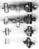
Some TV Sweep tube plates:
The left column ones being plain desgn.
The middle column having Barkhausen plates.
And the right column having the Cavitrap design. The top two also having the"winglets" extension on the outside from the Barkhausen plates. Better cooling of the "Barks" .
Another odd feature I occasionally see in the TV Sweeps are "waffled" inner edges on the g3 slot. 21JV6 and 35LR6 have them for example. Not a serrated edge, just crinkled. Maybe breaks up coherence of "snivet" oscillations?
Evolution of Cavitron design for similar tube:
https://www.diyaudio.com/forums/tubes-valves/281637-26dq5-curves-pin-2.html#post4498518
Attachments
Last edited:
The positive Beam Plates (very confusing when you keep referring to them as G3 slot lol) actually makes the knee less square, source: you 🙂 I looked through all the experiments you did with the different voltage on third element on that post you linked, a fricking gold mine if you ask me, in fact is it possible to share those traces on my blog? I want to do a few posts on the positive third elements, until now I never seen what effects positive beam plates actually have. Also I did not know what snivets were, I thought it referred to odd kinks in lines in some random places certain tubes experience (QQZ03-20 for example, search 8118 tube data to see the curves) but this makes more sense (also if you could explain exactly what these bursts are I'd appreciate it).
As for Cavitraps, I am referring to what you see on the right side there, and this was invented way way before those 1960s sweep tubes, actually in the 1920s... sad the industry was cheap and didn't care to look into it, the first and only pre-sweep tubes to do it is "48". Although seems fairly bad at first, the fact that cavitrap stricture is the ONLY secondary-emission-reducing thing there and the tueb is mostly kinkless is insane, no tube except that one ever did it far as I know. Although seems inefficient, actually it's 100V range SE power is unmatched by anything except very very last generation Tetrodes made 30-40 years after it...
Anyway I want to point out your experiments go into a great direction and I am so glad I joined this website, it's a goldmine so far for tube knowledge. I've not fully read through what you wrote, but when I get time I will make do and have a proper reply for ya.
Perfectly fine to copy or share the tube tracer curves, they are intended to be public access.
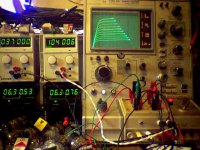
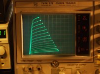
I'm using a Tektronix 576 curve tracer that has been modified for tube use. Mainly an extended (0 to 170 V ) step range, now with up to 15 step curves (was 10) and provision for automatically switching in two screen V supplies to the two tubes while under test. Very nice for matching or comparing tubes.
The high current capability of the 576 is handy for the big TV Sweep tubes. (2W, 10W, 50W, 220 Watt max selections) I'm usually using the 350 V collector sweep (50V/div). I also have a 700 V select available (100V/div, was 1500V originally, but I modded it down to 700 V, via full wave rectification, to get twice the available current on that scale)
Unfortunately it's down right now due to a bad LV power supply, and my attempts to fix it have been put off due to a bad toothache.
---------------
The "snivets" thing was explained in some now obscure article as the buildup of a charge cloud around the screen grid at high conduction, that oscillates back and forth (at VHF) thru the screen grid when the plate V suddenly drops to the knee V level or below. Apparently the neg. suppressor or beam plates prevent the charge cloud from dissipating to the plate quickly. Hence the positive V fix on g3 for this. The Barkhausen plate fix apparently helps too, maybe by making the oscillation freq. different at different beam positions.
The knee hysteresis problem I have seen mentioned in several books as an unstable buildup of the virtual-cathode charge position depending on the delta V direction when approaching the knee V. I have seen this on some very sharp knee tubes, not common. Usually some +V on supp. grid 3 will help, although beam plates have a much weaker influence.
Attachments
Last edited:
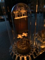
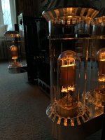
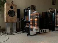
CRAZY AMP!!!
At first the images didn't show, and I saw some other huge triodes, now I see some V1505. Awesome.
Also, FWIW I believe the V1505 UHF triode has a Cavitrap serrated anode (assuming I am up to speed with the lingo), though it isn't carbonated.
I'd still like to be able to build something class A with them, but, even ignoring the kV HT required, the heater power is something else!
I got halfway through converting one into a table lamp. Even the PSU for that is large.
I have the original 1950s schematic for the Class B amp they were intended for, and 2 or 3 spare Ediswan V1505 tubes that look brand new, but I figure they dont have much resale value; untested, and no valve tester I know capable of checking them!
Last edited:
What are the 4 smaller valves at the bottom of the photograph?
I assume the driver stage? The schematic I have shows them driven by EL37 or KT61
I assume the driver stage? The schematic I have shows them driven by EL37 or KT61
Last edited:
EY500х4What are the 4 smaller valves at the bottom of the photograph?
I assume the driver stage? The schematic I have shows them driven by EL37 or KT61
Preamp 12ax7 + 76
 ! Congrats to this great craftmanship.
They make great night lights! I have a an old 4-400 that I put a filament transformer on and mounted in a walnut box.
- Home
- Amplifiers
- Tubes / Valves
- Very large tubes from radio transmitting tower