The MT-200 outputs are hard to hurt. I'm working on a new layout using ON Semi drivers and outputs. It's a little higher tech. It'll us a plug in protection card so the amp won't operate at all without the protection in place.
That's really nice! Same exact footprint and holes? I'm guessing the controller board will also have to be changed?
Which On-semi drivers will you be using?
Thanks
Do
The board is going to be about 1" shorter so it will fit into a DIYAudio chassis easier. The initial version of the control board will have it's own CPU. Each channel will have it's own control board and they will communicate with a master control board which controls the power supplies. I'm going to test MJL4298/4302 outputs first with MJE15032/3 drivers. I also found some more compact easy to get non inductive emitter resistors. If all goes as planned it should be one stop shopping with a single BOM from Mouser instead of parts from a few suppliers.
Hi Do,
Sorry for your loss. At the same time - it's good the amplifier is back in order.
Just for your information, a few issues we experienced earlier - actually related to building mistakes or inappropriate quality (or rating) of the parts used:
1) Thermo paste used in one of the builds was not electrically neutral - the amplifier was working for some time, then one of the paste chunks conducted, so there was a short of the output's collector to the heatsink (ground), accompanied with flash and smoke.
After changing the thermo-pads and re-assembling the OPS, everything worked again (nothing got really broken);
2) IPS module's compensation ceramic capacitors see almost rail-to-rail voltage at the high swing. The ones I used appeared to have 50V rating - one of them broke open, resulting in the local oscillation, caught by over-current protection. After replacing all those ceramics with 250V-rating ones everything worked perfectly.
So... issues may happen, however, NS series amplifiers are not that easy to kill 😉 It would be great to see some scope screenshots - to be confident there's no some kind of oscillation/ringing artifacts, etc.
Cheers,
Valery
Hi Valery,
Thanks for the kind words.
The thermal paste I use is non conductive as per vendor specifications. This time around I used micas with thermal paste and I usually use thermal pads Sil-Pad 600 or the red Keraterm (which I cannot find anymore in sheets). My friend made some thermal conductivity tests and told me that micas (if you thin them) are the best. I also did check conductivity with a good quality DM (Fluke) on chassis and all Sanken pins and it was ok.
I will check the BoM that was provided for the IPS and check the ceramic caps for voltage rating.
I'll try and get the Scope running and capture some screenshots
Thanks
Do
Jwilhelm, what output voltages and current does your power supply produce ?
Which supply are you referring to?
Hi Valery,Hi Do,
Sorry for your loss. At the same time - it's good the amplifier is back in order.
Just for your information, a few issues we experienced earlier - actually related to building mistakes or inappropriate quality (or rating) of the parts used:
1) Thermo paste used in one of the builds was not electrically neutral - the amplifier was working for some time, then one of the paste chunks conducted, so there was a short of the output's collector to the heatsink (ground), accompanied with flash and smoke.
After changing the thermo-pads and re-assembling the OPS, everything worked again (nothing got really broken);
2) IPS module's compensation ceramic capacitors see almost rail-to-rail voltage at the high swing. The ones I used appeared to have 50V rating - one of them broke open, resulting in the local oscillation, caught by over-current protection. After replacing all those ceramics with 250V-rating ones everything worked perfectly.
So... issues may happen, however, NS series amplifiers are not that easy to kill 😉 It would be great to see some scope screenshots - to be confident there's no some kind of oscillation/ringing artifacts, etc.
Cheers,
Valery
I have ceramic capacitors on the IPS boards that are rated for 50V. I hope that you are referring only at the compensation capacitors from base to collectors of 2sa1381/2sc3503 VAS transistors. These ones are rated for 100V. Is this ok?
Hi Valery,
I have ceramic capacitors on the IPS boards that are rated for 50V. I hope that you are referring only at the compensation capacitors from base to collectors of 2sa1381/2sc3503 VAS transistors. These ones are rated for 100V. Is this ok?
Exactly - those are the positions I had that issue with in my early prototype.
Assuming +/-50V (or so) rails, 100V rating is going to be fine.
Here's a schematic of the stereo version of the input supply. It uses a pair of 30VAC x 2 transformers to create +/- 42 and +/- 85VDC rails. Both channels share the same raw supplies. The inputs are operating in class A so there's no current fluctuation to cause cross talk between channels (this is in theory, yet to be tested in real life).
The high voltage rails are regulated and can be adjusted between +/- 40 - 75VDC output. If higher voltage is desired higher voltage transformers can be used. Voltage adjustment is made to the negative rails with R33 & R53. Positive rail voltage is adjusted to match negative rail voltage with R32 and R52. After voltage is matched all adjustments can be made via the negative rail adjuster. Positive follows negative. I've tweaked some values so the regulators will operate at 20mA while generating minimal heat with tiny heat sinks, but it can easily pass much more current.
The low voltage rails are pre-regulated down to +/-35VDC then regulated to a very low noise +/-15VDC with a couple excellent LDO regulators. These acn be adjusted to anywhere between 1.18V - 33V if desired via resistor changes. TPS7A4901/3001 can pass up to 200mA is required. I've tweaked this to provide 10mA with minimal heat with small heat sinks again.
Attachments
I was referring to the supply pictured in post #2508
Really nice work.
Thanks. The supply design is Valery's work. I just tweaked it a bit and did the layout. Now I just need to find the time to get a couple test chassis built and try it out.
That's C18 and C19 of the Vertical CFA, correct? If so, I'm pretty sure mine are 100V since Jeff suggested that voltage.
Thanks
Do
Thanks
Do
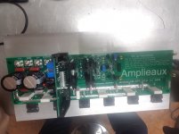
I've got a new version of the NS-output stage ready for testing with a dew design plug in protection board attached. No time to light it and try it right now though. he camera in my phone is smashed so I had to take this with a crappy old camera.
Attachments

You have incurred a great deal of effort in trying to offer me so many parts.😡I'll try to put together another batch of parts this weekend.
Hi Jeff,
Which output transistors are you using on the new NS Modular stage?
Have you moved away from the MT-200 Sankens because they are being discontinued?
Or is there another reason?
Excellent work from you guys.
Which output transistors are you using on the new NS Modular stage?
Have you moved away from the MT-200 Sankens because they are being discontinued?
Or is there another reason?
Excellent work from you guys.
I'm testing MJL4281/4302 outputs and MJE15032/33 drivers in this version to maintain the same output power handling of the Sanken MT-200s. I plan to test some cheaper single die outputs in lower power versions too.
We're testing these for a couple reasons. My personal preference is the Sanken devices but they are very large requiring a lot of length to the board. The upcoming obsolescence is a larger factor also. TO-264 devices allow for a 1.8" spacing with adequate space to cool the center devices so the board can more easily be mounted in a chassis with 300mm deep heat sinks. The new layout also allows for one stop shopping from Mouser. No more sourcing parts from multiple suppliers.
We're testing these for a couple reasons. My personal preference is the Sanken devices but they are very large requiring a lot of length to the board. The upcoming obsolescence is a larger factor also. TO-264 devices allow for a 1.8" spacing with adequate space to cool the center devices so the board can more easily be mounted in a chassis with 300mm deep heat sinks. The new layout also allows for one stop shopping from Mouser. No more sourcing parts from multiple suppliers.
A little issue I'm having... I've tested the amplifier with 8 ohms load and with sine wave and square wave and the output wave looks identical as the source which I measured first. I've done all the tests except for the high power test since I only have a 50W 8 ohms resistor to do it.
Since all other tests passed with flying colors, I've connected some 8 ohms speakers (El cheapo) to test with music and even at pretty high power everything seems to be fine... Now where I'm having issues is when I connect my Troels Gravesen ATS-4 speakers to the amplifier... They're 4 ohms but measure 4.2 ohms and are 91dB efficiency if I remember correctly. I start the amplifier with music playing but really faint, then raise the volume to the level I would normally listen to, but then the amplifier shuts down and I get the Overload message on the serial console (front led flashing to announce this as well).
It seems like the speakers are putting the amplifier under stress? Any pointers?
Thanks
Do
What voltage does the overload protection trip at when you power it from an adjustable supply? I've run these amps with 2R dummy loads in the past with no issues.
- Home
- Amplifiers
- Solid State
- Revisiting some "old" ideas from 1970's - IPS, OPS