Much of the literature uses ideal for a capacitor that follows I = CdV/dt.
Yes that would be an ideal capacitor. Are there any that behave that way? Certainly ones come very close.
Movement of the plates possibly measurable with laser interferometry.
Clearly audible. 🙂 You must not have meant rigid in all three dimensions.
So lets get back to the Pease model of DA where, let's be clear, V = RI and I = CdV/dt is all you have. You did tell jcx that you though you saw IM components in his sim (he never posted sine wave pictures BTW) so I still am wondering what you are trying to say.
Close enough to defy perception without voodoo and lining someone's pockets is fine by me.
Last edited:
Scott,
Did you read RNM's cite on DA models? Pease's approximation is a good one but there are better.
Where I think we disagree is on how close to an exponential curve the response to a step really is. You don't seem to have problems with the step stimulus not being perfect.
My next play will be to record the envelope of a bit of music and use that to modulate a sine wave around 100 hertz. What do you think the result will be when passed through a singe pole high pass filter with a corner frequency of 2 hertz?
Is the experiment clear to you?
Regarding capacitors, don't some of the best laboratory versions use air as a dielectric? In terms of DA, wouldn't that be rather imperfect according to the Simon7000 defintion?
Why air, when you can get nothing at all?
< vaccum kondensator | eBay >
My next play will be to record the envelope of a bit of music and use that to modulate a sine wave around 100 hertz. What do you think the result will be when passed through a singe pole high pass filter with a corner frequency of 2 hertz?
Is the experiment clear to you?
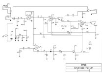
I don't think that's the right experimental model. Probably more like wiggling a tone control knob a little according to volume, but doing it fast enough that it's wiggling during one cycle of a sine wave.
If you wanted to use an envelope, an auto-wah circuit comes pretty close. The schematic below uses a couple of OTAs to implement the filter and an op-amp to rectify the audio to get the envelope.
For related amusement: The Technology of Wah Pedals
Attachments
Last edited:
My next play will be to record the envelope of a bit of music and use that to modulate a sine wave around 100 hertz. What do you think the result will be when passed through a singe pole high pass filter with a corner frequency of 2 hertz?
Is the experiment clear to you?
Steps are not music but that's beside the point.
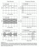
As for the experiment, no it's not clear. As a simple example the envelope of the sum of a 100Hz and 101Hz sine wave has a 1Hz component (worse yet it's technically multi-valued so not a function at all) so taking the envelope of the music is an extremely non-linear and/or an ambiguous operation. So you first have to show us what you consider the envelope of the music.
From now on these experiments should stated clearly with no ambiguity in any of the conditions.
What's the envelope of this...
Attachments

Last edited:
I don't think that's the right experimental model. Probably more like wiggling a tone control knob a little according to volume, but doing it fast enough that it's wiggling during one cycle of a sine wave.
If you wanted to use an envelope, an auto-wah circuit comes pretty close. The schematic below uses a couple of OTAs to implement the filter and an op-amp to rectify the audio to get the envelope.
For related amusement: The Technology of Wah Pedals
The folks who do synthesis used to look at an envelope as Attack, Sustain, Decay and Release. So that would be another module to test on a simple sine wave.
Scott,
As usual. I want the modulating signal well below the bandpass.
The folks who do synthesis used to look at an envelope as Attack, Sustain, Decay and Release
That's to simulate volume envelopes of individual notes such as one plucked string, etc. Not what you would get from finding an envelope for music with more than one note playing at a time.
The point I was trying to make is that an RC filter with DA is going to dynamically alter the corner frequency of filter. How fast it gets altered depends on what music is being fed into it, and DA absorption/de-absorption time constant(s) of the capacitor. If the DA is fast enough, at least for the most part, then the RC corner frequency would change slightly in time with the near-instantaneous signal voltage. To the extent the DA effective time constant is slower, then the RC filter corner frequency would change more with average signal level over a fairly short time period.
To get some idea of what the correct model would be for a given capacitor would require figuring out particular values for all the RCs in the ladder network, or whatever model is to be used. Then it would be possible to figure out how fast and how much the RC corner frequency would be expected to move for some particular music or music equivalent test signal.
EDIT: changed a few words hopefully for a little more clarity
Last edited:
Scott,
As usual. I want the modulating signal well below the bandpass.
Then what do you mean by modulation, simple multiplication? Then you can do it in your head by the convolution theorem there is nothing to filter. But you knew that so what do you really mean?
Attachments
Then what do you mean by modulation, simple multiplication? Then you can do it in your head by the convolution theorem there is nothing to filter. But you knew that so what do you really mean?
Maybe the way you would talk to one of your guys at work to get them thinking?
Maybe more likely to lead back to more arguing here. Different situation.
But I thought it was known that DA is a linear non-ideality in capacitors? DA means the capacitor appears to have a greater value at lower frequencies, not that its value changes with signal level.Markw4 said:The point I was trying to make is that an RC filter with DA is going to dynamically alter the corner frequency of filter.
But I thought it was known that DA is a linear non-ideality in capacitors? DA means the capacitor appears to have a greater value at lower frequencies, not that its value changes with signal level.
If an RC ladder is going to be the whole model, then it's linear. I'm not sure what the model is going to be. I think is has been claimed there is a nonlinear part to it, but I don't know what. I'm trying to suggest that somehow a model of some type needs to be specified along with ideal component values in order to move on more or less realistically. Once we have a model with some values, then we see about working through to everybody's satisfaction that new, or no new frequencies result, and the corner frequency does whatever it does given the model.
Then there is the issue of what does it sound like exactly to have the model in a circuit. In the end, the goal isn't to calculate corner frequencies, its to try to come to some understanding of how objectionable it might be to a few or many people. I know that part gets messy, but we do make amplifiers for people. Our goal should be to have the result of our efforts be agreeable to listeners, even though it's hard to define and measure. Tough.
Last edited:
I don't think that's the right experimental model. Probably more like wiggling a tone control knob a little according to volume, but doing it fast enough that it's wiggling during one cycle of a sine wave.
If you wanted to use an envelope, an auto-wah circuit comes pretty close. The schematic below uses a couple of OTAs to implement the filter and an op-amp to rectify the audio to get the envelope.
For related amusement: The Technology of Wah Pedals
The ICs in your attached schematic diagram are LM13700's.
Jan
Last edited:
An outstanding viola player I knew (sadly no longer with us) could listen to music on anything, even crappy little radios, he did not hear the physical layer, just the quality of musical "information".
This is a common quality amongst many musicians. Not all of course, but many.
To get some idea of what the correct model would be for a given capacitor would require figuring out particular values for all the RCs in the ladder network, or whatever model is to be used. Then it would be possible to figure out how fast and how much the RC corner frequency would be expected to move for some particular music or music equivalent test signal.
EDIT: changed a few words hopefully for a little more clarity
This has been done and models made from tests. A polar capacitor - which is what I wanted to be rid of has a zener across the C and a leakage R across the zener and C. A leaky diode.
Thus, if no DC bias on it, about 1v or less in one direction and Zener break down in other direction (max rated dcv). Used as a coupling cap (no dc bias) -- if signal peaks are less than .8-1v then the distortion does not rise to a high level. And the average consumer plays amps driving them with low signal input anyway...... average receivers and cost cutting products, played at low - moderate volume. And, if signal on a polar cap has greater peaks than approx 1 v the reverse voltage will also greatly shorten the life and DA will rise also.
If using a large value of C, then bi-polar is required if there is no DC bias (mostly input/output coupling cap apps). The back to back zener will prevent distortion above a volt peak.
http://www.waynekirkwood.com/images/pdf/Cyril_Bateman/Bateman_Cap_Sound_Part_5.pdf
THx-RNMarsh
Last edited:
This is a common quality amongst many musicians. Not all of course, but many.
Indeed... I just picked the best I knew of many! He was outstanding as a player and a teacher, and is much missed.
It seems they can filter out the issues in playback through some kind of memory only those with deep musical training tend to have. As though the music plays back in their mind, not really the medium. They even tend to make this similar expression if intently focused that I can best describe as an attempt to assemble / reassemble the missing musical information, like some kind of real time error correction.
Last edited:
This has been done and models made from tests.
Okay, maybe Simon7000 can pick a model he wants to use.
However, the more we talk about the effects on music, it seems like it might be a lot easier to run some music or a test signal through a capacitor, or a wire instead, and record the output of each to a wave file. We can see if anyone can hear a difference, and could subtract the two to see what the capacitor is doing to the sound.
While not an engineering model, it might be starting from a direction closer to the endpoint of interest, what does it sound like? Is is an audible problem?
Obviously, it might make sense to use a type of capacitor in dispute, that is to say, a pretty good one.
Mmm, perhaps this is the crux of where the difference lies, I suggest there is no missing musical information, at least as far as they are concerned.I can best describe as an attempt to assemble / reassemble the missing musical information, like some kind of real time error correction.
Okay, maybe Simon7000 can pick a model he wants to use.
However, the more we talk about the effects on music, it seems like it might be a lot easier to run some music or a test signal through a capacitor, or a wire instead, and record the output of each to a wave file. We can see if anyone can hear a difference, and could subtract the two to see what the capacitor is doing to the sound.
While not an engineering model, it might be starting from a direction closer to the endpoint of interest, what does it sound like? Is is an audible problem?
Obviously, it might make sense to use a type of capacitor in dispute, that is to say, a pretty good one.
Is it an audible problem? With electrolytic cap, it is. With films..... it is very hard to tell difference between them. Easier to compare a film against nothing -- wire. But films are very good. Just large physically and costly.
For the best of the best, even films are detectable under listening conditions you/I described. But, drop me into a listening room and an ABX/DBL tests and almost impossible to tell. So for all but Mastering engineers and perfectionists audiophiles, it does not matter. My concern is can I detect a change.... if only a minority can detect change then I would build to those people. The one percenters in audio. But thats just me. If the one-percenters are happy, likely all others will be also.
Listening evaluations of caps all over the planet for decades now have rank ordered them by DA. Lower DA sounds closer to a wire. Otherwise, use any PP type and you are generally, good to go for casual listening with modest speakers.
But, when are we going to stop using polar/bipolar coupling caps? No excuse for that practice still being used.
THx-RNMarsh
Last edited:
- Status
- Not open for further replies.
- Home
- Member Areas
- The Lounge
- John Curl's Blowtorch preamplifier part III