Have you checked - Audio level setting for playback. In Loopback all FFT softwares do not Control RTX. Some do and causes the output to lower level. Make Playback to Maximum for your loopback. It takes some time to understand how one software works as the documentation lacks such details.I have an observation for which I see no explanation up to now.
For the setting Out=20dBV, In=10dBV, sample rate 192kHz, the wideband noise floor is for the balanced output 6dB higher than for the unbalanced.
Pictures loopback, no signal (with signal alike), first balanced, second from the BNC out.
If the noise from both differential output pins would be uncorrelated I would expect only a rise of 3dB. 6dB you can only get if the balanced noise is some symmetrization of unbalanced noise.
Yes, it is important to state also the switch settings when doing measurements, since dBFS in itself is not the whole story. The units are calibrated, so the conversion is relatively straight forward, but I realize that it is easy to get the scales wrong.
I hope that, going forward, there will be support in some analyzer SW packages for automatic conversion. The switch settings are availvable on the USB interface (HID) and with this information it will be possible to scale the voltages in the program, thereby avoiding the manual conversion from dBFS to dBV, dBu or whatever is preferred.
The information about whether the unbalanced or the balanced output is used would have to be entered by the user though, since there is no way to get that information from the analyzer. The 6 dB difference can lead to confusion if not accounted for.
It would be great if analyzer SW like HpW Works, MATAA, audioTester, ARTA etc. would get built-in support for it. But this is not under my control in any way.
Hi Jens,
-Chris
That's my dream. Otherwise I'm very happy with it.It would be great if analyzer SW like HpW Works, MATAA, audioTester, ARTA etc. would get built-in support for it. But this is not under my control in any way.
-Chris
So 6 dBV is 2 x 0 Volt, which is also 0 Volt. Following this logic, all dBV values correspond to 0 Volt. This is so simple that even I might start to like decibels! 😀
No, seriously, you probably meant 1 Volt RMS = 0 dBV (see Wikipedia).
Yes exactly, it was a typo.
zfe,
You seem to be missing the content.
Assume the RTX6001 to be perfect and will never require calibration.
It is the Software that requires calibration or programing for each selector switch position.
For switch position 1; 0dBFS equals 100Vrms
For switch position 2; 0dBFS equals 31.6Vrms
For switch position 3; 0dBFS equals 10Vrms
For switch position 4; 0dBFS equals 3.16Vrms
For switch position 5; 0dBFS equals 1.00Vrms
For switch position 6; 0dBFS equals 0.316Vrms
For switch position 7; 0dBFS equals 0.100Vrms
Without knowing the attenuator switch position 0dBFS could mean any of 7 possibilities.
Many audio analyzers are auto ranging, The RTX6001 requires manual range adjustments by the operator.
Also the 6dB difference between balanced and unbalanced needs to be accounted for.
I am still in the process of setting up the RTX6001 on my bench. In the process I will fill in a spread sheet for the special numbers for each switch position for audio Tester V3 and post it here for inclusion in the wiki if there is interest.
To include all the autorange pieces parts would push the price point beyond reach.
JensH thanks for your time and effort producing the RTX6001. A first class machine.
DT
I grew impatient while we were anticipating the arrival of the RTX6001. There is an APx on my bench. See the attached BNC loopback; 1V out 96K FFT.
DT
That is a very nice looking plot! Which APx is it? The 555?
- OJG
In the process I will fill in a spread sheet for the special numbers for each switch position for audio Tester V3 and post it here for inclusion in the wiki if there is interest.
Sure! It would be cool if were not the only one adding content to the WIKI page.
I'd suggest to keep details to software-specific configuration related to the RTX in a separate section. I added a new section (2.3) for this.
Apart from this, I am not sure what you are
trying to point out here. If the data calibration in the software is
right (i.e., it matches the level switch settings), the test results
should be the same for the different level settings -- except maybe if
the signal gets lost in the noise floor, or if it is clipped due to a
mismatch of signal levels with the DUT.
Apart from the two extremal cases you mentioned, it is good to know where FS is located on your scale, as about 10dB below you get the best performance (distortion or noise wise) - which is e.g. important if you have a very low noise DUT.
At least I have a better feeling in terms of dBFS on where the ADC noise floor is located - which is important to know if you want to know if the noise floor you see is from the ADC of the DUT.
[...]
Is there any other software, that could be setup with different asio for input-output?
Sure: DiAna. 🙂
Cheers, E.
I know for the DiAna, Edmond 🙂
Wow! I didn't know that the asio4all have such capabilities!
Thanks, nyt!
Wow! I didn't know that the asio4all have such capabilities!
Thanks, nyt!
I know for the DiAna, Edmond 🙂
Wow! I didn't know that the asio4all have such capabilities!
Thanks, nyt!
It can be ... finicky... but it works in a pinch. That's what I used to measure the Motu into the RTX.
Yeah, I had seen your measurement with Motu at the REW but I don't immagine that this was with asio4all.
Very useful information, my congrats.
Just, complete some dac measurements with RTX on a dac via asio4all.
Very useful information, my congrats.
Just, complete some dac measurements with RTX on a dac via asio4all.
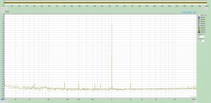
This is a sample “calibrated” balanced plot scaled in dBV.
The output switch is in the center position 1 volt, -20dBFS is selected in the steup options.
The input switch is in position #6, -10, 0.316.
Select options from the menu, click calibration and enter 316.22 mv and enter.
Sample size is 192K. 10 averages.
The computer is gen. 8, I7 8700k coffee lake.
This RTX 6001 rocks.
DT
Attachments
This is a sample “calibrated” balanced plot scaled in dBV.
The output switch is in the center position 1 volt, -20dBFS is selected in the steup options.
The input switch is in position #6, -10, 0.316.
Select options from the menu, click calibration and enter 316.22 mv and enter.
Sample size is 192K. 10 averages.
The computer is gen. 8, I7 8700k coffee lake.
This RTX 6001 rocks.
DT
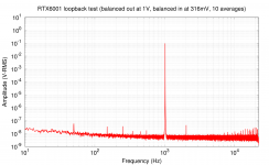
That's impressive! I actually didn't believe that mine is as good as this, so I repeated the loopback test with your settings. Wow, mine is the same!
(I should stop drooling over loopback results and get some real work done...)
Attachments
Hi mbrennwa,
As far as I understand you are using your own sw tool? If so, it shouldn't be to hard to get access to the HID interface on the RTX using libusb and possibly python.
I really wish there were a good tool that run on Linux.
My RTX 6001 is still in the box, as I haven't had time to look at it, so I haven't tried to access the HID interface.
Mogens
This is a sample “calibrated” balanced plot scaled in dBV.
The output switch is in the center position 1 volt, -20dBFS is selected in the steup options.
The input switch is in position #6, -10, 0.316.
Select options from the menu, click calibration and enter 316.22 mv and enter.
Sample size is 192K. 10 averages.
The computer is gen. 8, I7 8700k coffee lake.
This RTX 6001 rocks.
DT
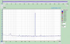
I followed your setup + vince3 Window.
Similar results...
Attachments
- Home
- Design & Build
- Equipment & Tools
- DIY Audio Analyzer with AK5397/AK5394A and AK4490