Looking at the schematic in post #49, a quick calculation (always a mistake!) gives me KB = 8.4 or 18dB. Do you get the same figure?
Absolutely right, and it would influence the main amp's gain at this rate if the "+" input of the opamp would be grounded.
But as it is connected to the input signal, we have KB / (1 + KB).
Exactly what we see in the simulation below.
Main gain stage's input is grounded, the opamp's "+" input is connected to the signal source, used for injection into the feedback. No error cancellation in this case, but the gain/phase are as shown.
Attachments

Same close-to-one-db - it does not depend on Vin. The higher BK is - the closer to 0db it will go.
Simple test - ground the output of K. Nothing noticeably changes except the level of distortion. This is tested many times.
Simple test - ground the output of K. Nothing noticeably changes except the level of distortion. This is tested many times.
The reason applying ODNF does not change the global gain is because the NFB target is the same global gain. But 18dB of NFB has been applied.
I find it easiest to look at the maths.
With the ODNF absent, the gain is ARX.
With ODNF present but OPEN LOOP (the opamp signal from the output grounded)
the gain is (AR + K)X
The ratio (AR + K)X / ARX is the excess gain which the closed loop system uses to control the output. This excess gain is 18dB. This is the gain that changes when you close the loop, rather than the overall gain.
the gain is (AR + K)X
In this formula (AR +K) does not look right. Why is it "+K"?
Let's forget about R - does not matter.
ODNF On:
Vo = Vi*AX - KBX / (1 + KBX)
ODNF Off:
Vo = Vi*AX
The gain is almost purely A in both cases.
Last edited:
Consider cutting the connection between the output and the input to K. K is now only connected to the input. Let's say R=1 and X=1.
Vo/Vi = (A + K)
Now, reconnect the output.
Vo/Vi = (A + K) / (1 + KB)
The gain has decreased by (1 + KB).
Vo/Vi = (A + K)
Now, reconnect the output.
Vo/Vi = (A + K) / (1 + KB)
The gain has decreased by (1 + KB).
OK, I finally see what you mean 😀
The parallel opamp-based front-end adds 18db of gain to the main front-end's gain in the summing point, which is then removed by 18db NFB loop.
OK, makes sense.
Output impedance decrease is around 10 times (from 0.3 ohm to 0.03 ohm) when ODNF is applied.
The parallel opamp-based front-end adds 18db of gain to the main front-end's gain in the summing point, which is then removed by 18db NFB loop.
OK, makes sense.
Output impedance decrease is around 10 times (from 0.3 ohm to 0.03 ohm) when ODNF is applied.

I find the "piggy-backing" of the opamps to the original design interesting. It seems to me to beg a question of balance: how much gain should be provided by the original input stage and how much by the opamps. If you think the opamps are much better amplifiers then you might dispense with the IPS. But the IPS is providing the voltage swing that the opamps can't so it is needed. I wonder if there are other factors that would determine the best balance?
I continue listening to my single channel prototype - running nicely, slowly building the 2-nd channel, thinking about the point raised by Brian about the best balance between the gains of the front-ends.
My approach right now - if I want an overall gain of the power amplifier to be 29db, I set the gain of the "main" (high swing) OPS to 29db. The opamps (or some other error correction circuit) adds 18db on top, that is "balanced" by 18db NFB loop. I believe, around 20db is a reasonable value, assuming the "main" front-end is linear enough.
My approach right now - if I want an overall gain of the power amplifier to be 29db, I set the gain of the "main" (high swing) OPS to 29db. The opamps (or some other error correction circuit) adds 18db on top, that is "balanced" by 18db NFB loop. I believe, around 20db is a reasonable value, assuming the "main" front-end is linear enough.
Better spectrum measurements
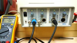
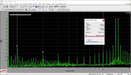
I've set up my recently received RTX audio analyzer in the lab - now I can show better measurements.
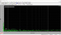
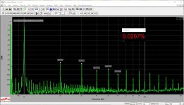
The first picture - note the noise floor with no signal - no noise / hum components above -120db line. Then THD for 1KHz and 20KHz, and IMD 14+15KHz go.
Listening to the amp - also through the analyzer's DAC - I would characterize the sound as "smooth and delicate" - no highlighting of anything, very comfortable listening in the near field (speakers are placed on the corners of a big table).
One 10pF bandwidth-limiting capacitor is added to prevent possible "ringing" when touching the input with something not grounded.
The design is rather mature now - easy to reproduce.
I'm thinking about a servo option for those who like rock solid zero offset, although right now possible fluctuations don't exceed +/-10mV.
I've set up my recently received RTX audio analyzer in the lab - now I can show better measurements.
The first picture - note the noise floor with no signal - no noise / hum components above -120db line. Then THD for 1KHz and 20KHz, and IMD 14+15KHz go.
Listening to the amp - also through the analyzer's DAC - I would characterize the sound as "smooth and delicate" - no highlighting of anything, very comfortable listening in the near field (speakers are placed on the corners of a big table).
One 10pF bandwidth-limiting capacitor is added to prevent possible "ringing" when touching the input with something not grounded.
The design is rather mature now - easy to reproduce.
I'm thinking about a servo option for those who like rock solid zero offset, although right now possible fluctuations don't exceed +/-10mV.
Attachments

V1.1
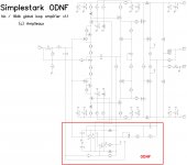
The one I have added is C20 (10pF). It closes the loop around the front-end at HF, preventing possible local oscillation when the input is touched with no ground reference.
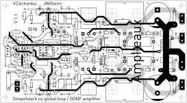
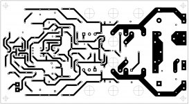
The 2-nd picture shows the real board view from the top (ground plane), the 3-rd picture - the ground plane is shown transparent to see the routing.
I have stayed with 18db loop gain in ODNF mode. If somebody wants to use the circuit in a pure no-global-loop mode - he can drop all the components within the red box, shorting TP2 and TP3 with a wire.
P.S. Added the bottom view of the board with the proper copper pours.
P.P.S. What still amazes me in this amplifier - the noise / hum level. This is the quietest amplifier I've ever designed - dead silent at idle. To be honest, I didn't expect it to be that quiet when I just started thinking about this design.
The one I have added is C20 (10pF). It closes the loop around the front-end at HF, preventing possible local oscillation when the input is touched with no ground reference.
The 2-nd picture shows the real board view from the top (ground plane), the 3-rd picture - the ground plane is shown transparent to see the routing.
I have stayed with 18db loop gain in ODNF mode. If somebody wants to use the circuit in a pure no-global-loop mode - he can drop all the components within the red box, shorting TP2 and TP3 with a wire.
P.S. Added the bottom view of the board with the proper copper pours.
P.P.S. What still amazes me in this amplifier - the noise / hum level. This is the quietest amplifier I've ever designed - dead silent at idle. To be honest, I didn't expect it to be that quiet when I just started thinking about this design.
Attachments

Last edited:
I have a couple of the original boards in stock. Valery sent me corrected files but was hinting that a new more compact layout is coming so I'm going to wait for that before having more boards done.
- Home
- Amplifiers
- Solid State
- No-global-loop amplification