regarding matching, this question has already been answered before somewhere in the thread, I believe.
regarding 4.7uF, use the lowest voltage but highest quality film cap you have in your parts bin.
you could even use a 10uF, 50V nichicon muse...
just try different thngs, let it be your workshop.
regarding 4.7uF, use the lowest voltage but highest quality film cap you have in your parts bin.
you could even use a 10uF, 50V nichicon muse...
just try different thngs, let it be your workshop.
Thanks Prasi, will use with the items that I have readily available.
What about the above post regarding the inverting of the polarity on the coupling capacitor? Any concern with your layout and do we need to look into this with the boards already ordered.
What about the above post regarding the inverting of the polarity on the coupling capacitor? Any concern with your layout and do we need to look into this with the boards already ordered.
Meaning the DLH can not use different supply voltage?...The advantage that I see is that it could operate under different voltage levels, something that must be clearly established in the design of the DLH....
I also found inherent destructive cross conduction problem for input signals larger than 3V in my simulation. I suggest some kind of input over voltage protection.
Please edit and state these limitations on post #1 before too many people use other supply voltage or large input signal that will destroy the output mosfets and kill the speakers.
Looks like its difficult to procure BC550BP / BC560AP transistors in India. Is there any equivalent transistors which are direct replacements that can be considered?
Thanks
Thanks
Hi
Thay to look for BC550C/BC560C, these transistors produced by several companies.
You can get them from Ebay also, I don't think you need to worried about fakes in these case. Those are cheap signal transistors few Cents value. It really does not worth to produce counterfeit it. 20pcs BC550C NPN Low Signal General Purpose Transistor TO-92 NEW | eBay
Meaning the DLH can not use different supply voltage?
That was a comment related to a comparison of the DLH with a specific scheme of post 348. Only that.
Likewise, all the component specifications that were proposed to develop the DLH have been an optimal compromise choice to obtain the quality parameters that it achieves.
If you intend to use other supply voltages, you simply have to rethink other specifications for the components: such as maximum allowed dissipations, values in ohms and everything that is considered necessary and related to that change. This is necessary since there is no mechanism that can limit the power dissipation in both the small signal transistors and the mosfets, with the power supply voltage rising above the reference voltage (15.67 V), once adjusted the bias.
I also found inherent destructive cross conduction problem for input signals larger than 3V in my simulation. I suggest some kind of input over voltage protection.
Please edit and state these limitations on post #1 before too many people use other supply voltage or large input signal that will destroy the output mosfets and kill the speakers.
I make this clarification again: the DLH was developed as it was presented bearing in mind as many quality premises as possible. The input signal that was anticipated was the one that can deliver the output of a typical CD player (2 V RMS).
Whoever needs to adapt it to build it with other values of available elements, can do it perfectly, but will have to recalculate it without losing quality as its main objective. It is not impossible, but whoever has to do it will have to resort to his own abilities.
As a simple data when analyzing the scheme of post 1: assuming that both values of Vgs are similar, the potential difference between the collectors of the BJTs is equal to that of a single rail (around 15.67 V). The rest of the voltage (the other 15.67 V) are distributed proportionally between the two trimpots and the fixed resistance of 390 ohms. From that situation, we can predict the collector current of any of the BJTs, since they are extremely very similar. From then on, all calculations and possible considerations could be reconsidered. All exposed is with short-circuited signal input.
Last edited:
Please refer post no. 74 by designer. He makes it clear regarding what grade of transistors to be used.Looks like its difficult to procure BC550BP / BC560AP transistors in India. Is there any equivalent transistors which are direct replacements that can be considered?
Thanks
Yes Diego, but CDs are disappearing. I think you are also aware that DACs with 3V RMS output are incrasingly being offered. These would be fatal when used by DLH users due to the inherent cross conduction on large input signal without any input limiter. You can save the DLH from being destroyed by publishing clear limitation and limiter as preventive countermeasure.... I make this clarification again: the DLH was developed as it was presented bearing in mind as many quality premises as possible. The input signal that was anticipated was the one that can deliver the output of a typical CD player (2 V RMS)....
Please refer post no. 74 by designer. He makes it clear regarding what grade of transistors to be used.
Thanks Prasi got it then I need to buy some BC550 and 560 in bulk to test the hFE values to arrive the right one per designer.
I personally just grabbed random samples of BC550/560 - it worked pretty well and maybe I got lucky. However, BC550/560's are as Hugh says, are 'cheap as chips'. 🙂
Has anyone else built and fired up this amp besides the OP and myself? I lost track...
Has anyone else built and fired up this amp besides the OP and myself? I lost track...
Thanks XRK, yes they are really cheap but locally I have to insist for 'C' grade series and then check the hFE values.
I am now worried with the above comments of input signal should be <2V from the preamp to the DLH. That limitation needs to be considered while pairing it directly with DACs or line stages with high voltage outputs?
I am now worried with the above comments of input signal should be <2V from the preamp to the DLH. That limitation needs to be considered while pairing it directly with DACs or line stages with high voltage outputs?
I missed the discussion, what is the worst thing that happens if input >2v? p-p or rms, and does it blow amp up?
Yes Diego, but CDs are disappearing. I think you are also aware that DACs with 3V RMS output are incrasingly being offered. These would be fatal when used by DLH users due to the inherent cross conduction on large input signal without any input limiter. You can save the DLH from being destroyed by publishing clear limitation and limiter as preventive countermeasure.
if it is necessary to adapt it for a DAC output of up to 3 V RMS, simply increase the resistor from 56 ohms to 120 ohms (in the feedback network). A much more simple and better solution than any input limiter, from many aspects. A very slight adjustment of BIAS and OFFSET may be necessary.😉
Last edited:
I missed the discussion, what is the worst thing that happens if input >2v? p-p or rms, and does it blow amp up?
As designed, my simulation show cross conduction at ~8V peak output corresponding to >2V RMS (2.83V peak) input. Will happen at lower input signal if gain is increased, or higher input signal if the gain is decreased as Diego explained above. A point I think DLH users need to clearly understand.
Attached are simulation results showing output voltage and current through the 0.15 ohm source resistors at input voltage 3V and 5.66V peak into a 2 ohm load. I think some kind of input limiter is a good insurance to avert potentialy fatal result when the DLH is being used with a source with high voltage output like the 40V capable Aksa Lender preamp.
However, cross conduction behavior of the DLH Buffer is more benign. Last attachment show that the DLH Buffer has the potential to survive occasional 40V peak input without any limiter.🙂
Attachments


As designed, my simulation show cross conduction at ~8V peak output corresponding to >2V RMS (2.83V peak) input. Will happen at lower input signal if gain is increased, or higher input signal if the gain is decreased as Diego explained above. A point I think DLH users need to clearly understand.
Attached are simulation results showing output voltage and current through the 0.15 ohm source resistors at input voltage 3V and 5.66V peak into a 2 ohm load. I think some kind of input limiter is a good insurance to avert potentialy fatal result when the DLH is being used with a source with high voltage output like the 40V capable Aksa Lender preamp.
However, cross conduction behavior of the DLH Buffer is more benign. Last attachment show that the DLH Buffer has the potential to survive occasional 40V peak input without any limiter.🙂
It would be interesting to indicate the scheme that has been simulated and under what type of adjustments the offset, bias and mode of operation of the output have been set, in order to analyze the exposed results.
I can do better Diego, I attach the Ltspice circuit I use. But simulation has little value to you with working unit, direct measurement is always the best.It would be interesting to indicate the scheme that has been simulated...
Attachments
I can do better Diego, I attach the Ltspice circuit I use. But simulation has little value to you with working unit, direct measurement is always the best.
OK.
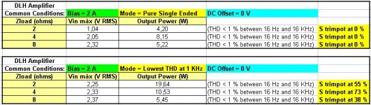
I upload a box of limitations referring to the version shown below. I hope it will be useful to clarify your doubts. Keep in mind that depending on the settings of the trimpots for DC Offset, the operating mode chosen for the output (SE / PP), Bias, the value of the load and the voltage of the power supply, certain limitations may appear (limitations that also exist in the PLH, for example).
If you need to operate the DLH from the output of a DAC with voltages greater than the maximum 2 V RMS, it may be necessary to decrease the closed loop gain in the same rate of increase of input signal over the reference of 2 V RMS. With 3 V RMS, for example, increase the 56 ohms x 1 W resistor of the feedback path to 120 ohms x 0,5 W.
Note that using a typical CD signal, you could adjust with almost the majority of the load options (except for 2 ohms operating in pure single ended). The mosfets would operate within their safe limits.
Attachments
Last edited:
I have no doubt Diego, I know that within limit, the DLH sounds really good, it simply does not have the power capability I want. However, I am working on the buffer to be used with my tube preamp....I hope it will be useful to clarify your doubts. ...
i'm on jlh's thread for many years and I am super fan of simple schema.
I discover this theard and this DLH with great pleasure and I think I'll try it because he's a good candidate.it is so simple that a P2P assembly is needed for me !!
I finished an umpteenth version of a jlh and I start that one to see.
thank you for this project which looks very promising !
I discover this theard and this DLH with great pleasure and I think I'll try it because he's a good candidate.it is so simple that a P2P assembly is needed for me !!
I finished an umpteenth version of a jlh and I start that one to see.
thank you for this project which looks very promising !
- Home
- Amplifiers
- Solid State
- DLH Amplifier: The trilogy with PLH and JLH amps