Where these changes continuous or like steps? If they where indeed continuous like a warble that would indicate that the buffer don't work kas intended. If distinct steps, how often? Please, if possible, post a short .wav snippet?
//
They felt continuous but I guess changes on the Mhz clock are heard as continuous and that is as intended (If I understand Soren right).
The tests where made 2 years ago so I have to search for the audio files.
Or simply repeat the test as soon as I have time.
The whole test setup might be moot if my source clock on the AES Line is somehow corrupted (The AES source is a RME UFX device) because multiple DAMs in parallel would of course react the same way to those fluctuations and would be practically in sync...
I think I did said something early on, it's basically a digital PLL with a 0.1 hz loop filter, the frequency is updated when there is one hz or more difference.
The FIFO size is 1 mS, size in words depends on samples rate.
OK so you don't supervise the level of utilisation of the buffer? Would this not be a better strategy? Say if the incoming speed is varying around a centre frequency, you would really not run out of buffer but you will have constant change of the clock to try to follow the source. If you in this situation instead checked for if a high or low mark (75% of the buffer?) is reached, then change clock... This would make the clock changes be very rare. A guess from me is that when you order the clock to change it will have more jitter for a while before it settles? If you make constant changes this would not be so good?
Is there a way to supervise the clock orders in SW? Something for a FW update to send on the serial? (if not flooded!)
In your tests, what have been the pattern of clock orders?
//
The input to the PLL is the FIFO utilization....
 OK. Just trying to figure out the reports on change i sound with different sources. I have experienced it myself. No bad sources, good but different. Maybe they are all imaginary. Some observability would help figuring which way it is.
//
Hi Soren
Are you 100% positive that multiple Dams in parallel have exactly the same delay?
As I wrote I did a test with recording multiple takes of the same track through the dam and with reversing polarity I heard that the takes had different phase relationships and even worse, they changed during the course of the track. As if the fifo adjusted...
But of course my testing setup might have been faulty....
Sounds exactly like RME's Steadyclock trying to syncing to more than one clock to me. If you repeat this test with the PCM4222EVM as the master, the RME synced to it and the DAM1021 synced to the RME's digital out the problem will likely vanish.
//
It is pretty hard to get totally rid of jitter. Furthermore, on a pc you need to be careful to ensure bit perfect operation. I hear significant differences between asio and kernel streaming in my setup. It would be cool if the dam DAC would get a mode to validate input is bitperfect. To make sure that bit perfectness is out of the equation...
A way to implement this would be to add a serial command to dump the first 256 input samples. The microcontroller should wait with dumping until input is non zero so that synchronization takes place. This feature would be helpful to analyse interface issues and bit perfectness.
!541
Hello,
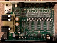
I've changed a bit on my 1541 and achieved good. Attached are some pictures:
1. 1541 currently.
2. New filters.
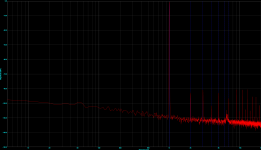
3. Spectrum before the last changes.
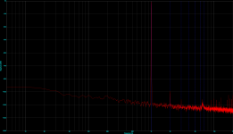
4. Spectrum up to date.
Next, I'll think again about the USB input, always grateful for suggestions,
Greetings JJ
Hello,
I've changed a bit on my 1541 and achieved good. Attached are some pictures:
1. 1541 currently.
2. New filters.
3. Spectrum before the last changes.
4. Spectrum up to date.
Next, I'll think again about the USB input, always grateful for suggestions,
Greetings JJ
Attachments

Hello,
I've changed a bit on my 1541 and achieved good.
Very nice, 3rd and 5th order are about 20-25db down. Impressive!
Regards,
Danny
JJ, is it your own brewed filters? Whats the strategy? Will you share them?
//
Hello TNT,
I have tried my own filters but have not achieved anything good. Then I tried with different combinations of available filters, was also not optimal.
My current strategy is to outsource the first upsampling stage to the MAC. This works very well. In the second upsampling stage, I'm currently using the standard minimum phase filter, but that's certainly a question of faith, and others are doing well too. Worth mentioning is the profit from the removal of the 2 Hz IIR high-pass filter.
Attached the current filter file.
Greetings JJ
Attachments
Hello,
I've changed a bit on my 1541 and achieved good. Attached are some pictures:
1. 1541 currently.
2. New filters.
3. Spectrum before the last changes.
4. Spectrum up to date.
Next, I'll think again about the USB input, always grateful for suggestions,
Greetings JJ
That is some serious cannibalization, you should have kept the amplifier and just routed the direct resistor ladder output to the output connectors....
But what step caused the distortion to drop ?? I don't believe that the hardware itself is capable of such low distortion....
And in your opinion, what did you gain by removing the highpass filter ?
From your pictures it is not clear of which "filters" you speak that are cause of the change. Filters of the power supply (first picture) or software filters (second picture).Hello,
I've changed a bit on my 1541 and achieved good. Attached are some pictures:
1. 1541 currently.
2. New filters.
3. Spectrum before the last changes.
4. Spectrum up to date.
Next, I'll think again about the USB input, always grateful for suggestions,
Greetings JJ
Worth mentioning is the profit from the removal of the 2 Hz IIR high-pass filter.
Greetings JJ
Is this what improved the distorsion figures? Do you have before / after measuring for only this change? Or is it omiting the upsampling stage in the DAM that made the improvemnt? Or do you need both?
So you can now only run 384 khz files - right?
//
That is some serious cannibalization, you should have kept the amplifier and just routed the direct resistor ladder output to the output connectors....
But what step caused the distortion to drop ?? I don't believe that the hardware itself is capable of such low distortion....
And in your opinion, what did you gain by removing the highpass filter ?
Hello Sören,
cannibalization is a funny term, 🙂, your output stage is a great headphone output, but I do not listen with headphones and my consistent Symmetrical preamp likes consistently symmetrical signals with 500-2000 ohms source impedance, for me the only difference level comes in the final stage , I see no sense in a symetrical signal to dismyrate and then to sync again.
You should not devalue your hardware, the measurement is real. ;-) However, the progress is not only in the hardware but also in software search. I've tried a bit of what I've been thinking about for decades, and suddenly there was that result. I still need a bit to describe it correctly and briefly, and I am not sure yet if I will publish it here.
The missing high pass is something everyone should try for themselves. With me he has tonally improved the entire listening area. But I'm not surprised, low-frequency IIR high-pass filters have never been the best choice. What do we really need it for?
The 1541 is a great device, even in production condition. All my changes have been made only to adapt to my listening habits and my tonal ideals, in my chain and in my ears it now works "better", that does not have to apply to others.
Greetings JJ
From your pictures it is not clear of which "filters" you speak that are cause of the change. Filters of the power supply (first picture) or software filters (second picture).
Hello zfe,
both are modified, the filters of the power supply and the digital filters internally and externally.
Greetings JJ
Is this what improved the distorsion figures? Do you have before / after measuring for only this change? Or is it omiting the upsampling stage in the DAM that made the improvemnt? Or do you need both?
So you can now only run 384 khz files - right?
//
Hello TNT,
no, if the 2Hz filter nor the upsampling filter has changed the distortion, it is the hardware in the DAC to the other software outside the DAC. Surely you could insert the software change in the DAC, but that can only Sören.
Greetings JJ
Is this what improved the distorsion figures? Do you have before / after measuring for only this change? Or is it omiting the upsampling stage in the DAM that made the improvemnt? Or do you need both?
So you can now only run 384 khz files - right?
//
... yes, I can only process 352 / 384kHz signals in the DAC, the first upsampling stage is outside the DAC ...
A filter (before FIR2) can hardly do better than playing the real thing - a 384 kHz test signal (real no upsampling).
Have you tried to vary the signal level (of the input samples) slightly? Perhaps you luckily landed on a sweet spot relative to the resistor errors.
Have you tried to vary the signal level (of the input samples) slightly? Perhaps you luckily landed on a sweet spot relative to the resistor errors.
- Home
- Vendor's Bazaar
- Reference DAC Module - Discrete R-2R Sign Magnitude 24 bit 384 KHz