Clever simulation. You changed my mind on this subject, thanks.I simulated mine two CFAs, one with wide bandwidth of 80 dB of LG and the same amp, but now instead of simple resistor loaded IPS it is active loaded with CMs and it has not so wide bandwidth but with 120 dB LG up to 1kHz.
Damir
How well would you expect the performance to be if the circuit was laid out and built by a non-professional? How about the average builder?
-Chris
I see. You think, I am non-professional and average builder.
That's not much to write home about.
BTW: It is not an EC (AKA: Error Correction) circuit
Have nice new year
Reodor
For the Power level and freq and Z it is excellent.... but at 200W or less (the design/spec output), it is well under .001%. .0002-0005% 1W-200W into 2 Ohms.

Much better at higher load Z -----> 🙂 eg 8 Ohms.

Measured..... not SIM
CFA -- 400+ v/usec; very low noise.
THx-RNMarsh
Last edited:
I cant recall the exact numbers we got - but easily ten times or more worse THD due to wiring and grounding practices.
Not it would be a bad amplifier performance at these low levels, but is unnecessarily throwing away careful circuit design and performance.
THx-RNMarsh
Not it would be a bad amplifier performance at these low levels, but is unnecessarily throwing away careful circuit design and performance.
THx-RNMarsh
Last edited:
which part of your profile tells us otherwise?I see. You think, I am non-professional and average builder.
I cant recall the exact numbers we got - but easily ten times or more worse THD due to wiring and grounding practices.
Not it would be a bad amplifier performance at these low levels, but is unnecessarily throwing away careful circuit design and performance.
THx-RNMarsh
Which amp are you talking about?
It's not hard to figure out Bimo's abilities if you poke around the forums. He's a very respected designer in his home country. Anistardi's Blog | Elektronika dan Pemograman | Halaman 2which part of your profile tells us otherwise?
Now, even it can reduce a little bit.
Bimo, you can improve your FFT plot by shortening input capacitor (I suppose it is not, from FFT plot).
Happy New Year to you and all DIY-ers, audio professionals too.
Damir
Bimo, you can improve your FFT plot by shortening input capacitor (I suppose it is not, from FFT plot).
Happy New Year to you and all DIY-ers, audio professionals too.
Damir
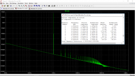
Ok. I will do.
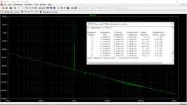
My amp use typical "blameless" topology with TMC compensation and use buffer before LTP as Keantoken mention it.
Ok. I will do.
This is the result.
Attachments
This is the result.
Use Windowing Function, Blackman for example.
I see. You think, I am non-professional and average builder.
I don't think it's you Chris is necessarily pointing at. But there are plenty of others here that might get the wrong picture.
Here is an example.
http://www.diyaudio.com/forums/solid-state/315343-reasons-oscillations-audio-amplifiers-elimination.html
Last edited:
Which amp are you talking about?
Anyone's amplfier down below -100dbv.
Being shown as example is DaDod's design.
It has taken the gang in Bangkok fab about a year to get it this low. First was they needed better analyzer to read low enough. I returned twice to sort out why the THD being shown to me was higher than I measured at my Calif home lab.
First time I had to sort out what was grounding and noise issues totally related to the test setup between DUT and AP analyzer and computer.
Second trip, was all about incorrect grounding/wiring practices within the DUT/PA.
This backs up others here that say SIM numbers can be hard to realize in practice without experience and care in building such low noise/distortion levels.
THx-RNMarsh
Last edited:
That is an obvious possibility, but unless you measured that base current's degree of nonlinearity, it is speculative.
But that's exactly what I did. I let the base current flow through a resistance and measured the distortion.
More importantly, if we accept that it is nonlinearity in the base current, you still failed to explain the source of that nonlinearity and whether the magnitude of the postulated source of the nonlinearity was sufficient to cause the observed results.
But, I repeat, I did, on p146 of APAD 6th edition. It is clearly pointed out that the job of the NFB loop is achieve linearity at the amplifier output, and to do this it may employ all sorts of non-linearities inside the amplifier. Look at the horrible distorted waveform on the VAS output compared with the output stage output.
Hi Douglas,
Of course the base currents are distorted, otherwise no distortion across the input impedance (rather obvious, I would say). But where does this nonlinearity stem from? Is it the nonlinear Miller capacitance, the Early effect and/or a nonlinear loading of the current mirror or VAS?
Happy New Year,
Edmond.
Any non-linearity anywhere in the amplifier will cause the input currents to be non-linear, because the NFB loop forces the amplifier output to be linear.
Hi Doug,
I have also chased the signal through an amplifier and have seen what you are talking about. The signal into the output stage doesn't look very nice compared to what comes out of it.
I have also found that extremely tightly matched diff pairs help to lower distortion. Not a surprise since this is the stage where input signal is compared to what comes out for correction.
-Chris
Hi bimo,
I wasn't referring to you or anyone specifically. Just that the average designer / builder is not going to have the same success that a professional generally will. One major skill that is unknown is how well you lay out a circuit board. I have no idea how good you are, so I'm not about to comment on it.
It is common that everyone feels their skills are higher than they actually are. That's just being human. You may or may not fit into that catagory.
-Chris
I had spend hours to read this thread silently. Nice moments, very instructive, always in a friendly atmosphere. Changed my mind on some points, thanks for this gift.
Happy new year, full of success, to all the Diyers and specially all the participants of this thread, including those that are not here any more.
Special thanks to Bob, for his work full of generosity, expertise, open and objective mind, wonderful curiosity.
Happy new year, full of success, to all the Diyers and specially all the participants of this thread, including those that are not here any more.
Special thanks to Bob, for his work full of generosity, expertise, open and objective mind, wonderful curiosity.
- Home
- Amplifiers
- Solid State
- Bob Cordell's Power amplifier book