I simulated my circuit it in LTSpice, and was surprised that the effect of input current distortion was much much lower in the simulation than what is found in Self's book...
Now lately I also got Bob Cordell's book Designing Audio Power Amplifiers (2011 edition).
And wow, it's a really in-depth book on the subject, but I found no reference to input current distortion whatsoever...
So then I was thinking again: Self says that it is the nonlinear Ib (base current) that creates this distortion as it flows through the serial input resisitor (or the feedback network). Now LTSpice MUST account for that, don't you think? Isn't the exponential Ib-Vbe curve the basic equation of a BJT?
So this would be my question. Is it possible that the simulation is right that input current distortion is really not of major concern as long as I don't aim for ultra low distortion? But then what did Mr. Self measure in his book?
If you ever start thinking that a simulation proves the measurements wrong, alarm bells should start ringing. THD measurement is very straightforward with the right equipment and it's not hard to do it right.
On the other hand, SPICE simulation, while an extremely powerful tool, has to be wielded with great care. All semiconductors of the same type are absolutely identical, which is not how the real world works, and can lead to some subtle errors.
SPICE also uses approximations to model the variation of hfe with Ic, and Early effect, in BJTs.
I think these factors are enough to explain any differences between your simulations and my measurements.
I believe Self talks about non-linear input capacitance to the substrate/supplies rather than the exponential Ib/Vbe. The input cap is nonlinear versus voltage, and thus causes distortion with appreciable input R.
He also gives a solution: bootstrapping the supplies will swing the input cap 'far side' with the signal so will keep the voltage across it constant. Works best with gain of one stages of course.
Jan
Hello Jan.
I suspect you are thinking of my work with opamps. I have never built an amplifier with FET inputs. Life's hard enough as it is...
THD was reduce when I use opposite gender of buffer and LTP transistor. Why?
It's probably very dependent on how it was done. If well executed, P or N won't make much of a difference.
Hello Jan.
I suspect you are thinking of my work with opamps. I have never built an amplifier with FET inputs. Life's hard enough as it is...
OK, I stand corrected. I indeed was thinking about your opamp work with bootstrapped supplies.
Jan
It's probably very dependent on how it was done. If well executed, P or N won't make much of a difference.
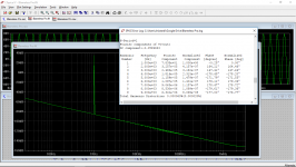
I use 90VDC PSU and got THD at 384W/8Ohm, 1kHz -> 0.000061%
H2 was slightly reduce.
Attachments
I use 90VDC PSU and got THD at 384W/8Ohm, 1kHz -> 0.000061%
H2 was slightly reduce.
Have you published a schematic of this Amplifier?
I have some concerns about the assimilation of Fairchild...
The BC550C is now being sold in Mouser only as "OnSemi/Fairchild". As I understand, Fairchild and OS versions of the BC550C were different. I wish I knew more details about the differences, for instance Rbb, but I do know the OnSemi parts didn't work well in my Kmultipliers.
Any idea which version of the part is being sold as BC550C now?
Hi Bimo,
Actual measurements will disappoint you ... greatly.
-Chris
No, If implementation is good. Dadod and Astx did prove it.
I have some concerns about the assimilation of Fairchild...
The BC550C is now being sold in Mouser only as "OnSemi/Fairchild". As I understand, Fairchild and OS versions of the BC550C were different. I wish I knew more details about the differences, for instance Rbb, but I do know the OnSemi parts didn't work well in my Kmultipliers.
Any idea which version of the part is being sold as BC550C now?
I think they're both Fairchild's, because it carries Fairchild's packaging codes. The OnSemi TO-92's were discontinued for a period already leaving the SMD BC8xx's only.
Buy 100 pieces from a trusted source and measure them, or if you lack the patience, contract with a measurement house to perform the measurements for you.Any idea which version of the part is being sold as BC550C now?
Why trust any anecdotal evidence you might read here, especially since members often purchase their "ON Semiconductor BCxxxx" devices from eBay and AliExpress, then post results claiming the measured devices were Genuine.
Hi bimo,
I have built enough circuits and measured them to know, and I do match my transistors very closely using a jig I designed for that very purpose.
Notice that I am not saying the design isn't good. All I am saying is that your quoted "measurement" will not reflect real life. It would help if you didn't post such optimistic figures. It doesn't do anyone any good.
-Chris
This came from your simulated circuit. In real life it will not be as good, no matter how good implementation is.I use 90VDC PSU and got THD at 384W/8Ohm, 1kHz -> 0.000061%
I have built enough circuits and measured them to know, and I do match my transistors very closely using a jig I designed for that very purpose.
Notice that I am not saying the design isn't good. All I am saying is that your quoted "measurement" will not reflect real life. It would help if you didn't post such optimistic figures. It doesn't do anyone any good.
-Chris
But it can close to simulation. Dadod implementation was 2,7x sim result. I do not know your implementation. 100x from sim result? 🙄
Hi bimo,
I don't think it will be close to simulation given those extraordinary low THD numbers. Maybe not 100X worse (but it could be depending on the circuit layout).
There are too many factors that can reduce performance. Devices differing from each other and from the bogey device the simulator uses for one. PCB layout can destroy performance easily. Even voltage dependence resistors and capacitors have will prevent reaching such a low level of THD. If your simulation indicates 0.004 %, I can see it being close, but you are quoting 0.000061%. Even the ability to measure distortion that low is beyond any normal test procedure. It doesn't take much to throw off a circuit that is supposed to perform at levels like that.
I'm reasonably certain that the real circuit will not perform anywhere near the numbers you quoted. Not because it is a bad circuit, or you aren't a good builder. It's because extremely high performance is very difficult to actually achieve.
-Chris
I'm reasonably certain that the real circuit will not perform anywhere near the numbers you quoted. Not because it is a bad circuit, or you aren't a good builder. It's because extremely high performance is very difficult to actually achieve.
-Chris
I agree, it is very difficult to achieve. But it is possible to achieve 0,0001% PGP. Although, my amplifier THD in 20kHz is much higher than that amplifier. But for high power amplifier, it is good enough.
Hi bimo,
I don't think it will be close to simulation given those extraordinary low THD numbers. Maybe not 100X worse (but it could be depending on the circuit layout).
There are too many factors that can reduce performance. Devices differing from each other and from the bogey device the simulator uses for one. PCB layout can destroy performance easily. Even voltage dependence resistors and capacitors have will prevent reaching such a low level of THD. If your simulation indicates 0.004 %, I can see it being close, but you are quoting 0.000061%. Even the ability to measure distortion that low is beyond any normal test procedure. It doesn't take much to throw off a circuit that is supposed to perform at levels like that.
I'm reasonably certain that the real circuit will not perform anywhere near the numbers you quoted. Not because it is a bad circuit, or you aren't a good builder. It's because extremely high performance is very difficult to actually achieve.
-Chris
+1
Anatech is correct --- It has taken a long time building Damir's design. Grounding paths, wiring paths, smallest loops, routing etal....... but finally getting the thd down to the levels showing the designs full potential to EC. -- virtually complete EC... partially made possible due to the CFA characteristics.
At the moment, we are here - 4 Ohms --->

THx-RNMarsh
At the moment, we are here - 4 Ohms --->
THx-RNMarsh
Last edited:
Keeping the differential source impedances the same can improve PSRR if the LTP is not cascoded. But other than that, and DC offset effects, the linearity gained from optimizing differential source impedances is usually only fractional and not necessarily worth designing the circuit around.
After all, if it matters that much you can just add buffers to your LTP. I don't know why this seems to have gone out of favor, but it does help enormously with the robustness of a BJT input amp. All the chips do it, why not us. 😕
Tom Holman put EF buffers in front of both sides of the LTP in his APT-1 many years ago, and that design was always well-received and a very good performer.
Cheers,
Bob
If you ever start thinking that a simulation proves the measurements wrong, alarm bells should start ringing. THD measurement is very straightforward with the right equipment and it's not hard to do it right.
On the other hand, SPICE simulation, while an extremely powerful tool, has to be wielded with great care. All semiconductors of the same type are absolutely identical, which is not how the real world works, and can lead to some subtle errors.
SPICE also uses approximations to model the variation of hfe with Ic, and Early effect, in BJTs.
I think these factors are enough to explain any differences between your simulations and my measurements.
The increase in distortion you described with source impedance of 1k compared to nearly zero was not subtle, and SPICE, even with its approximations to the real world, should have picked it up, especially if decent transistor models are being used. SPICE and real-world measurements each have their individual shortcomings, and to blindly believe in either one's results alone is unwise. When they conflict significantly, it is important to drill down to find and understand the source of the difference. It was never clear from your discussion in the book as to what you thought the specific technical reason was for the increase in distortion with the increase in source impedance. An increase in source impedance at some point will not surprisingly lead to an increase in distortion, but why it led to an increase of the degree you reported at the source impedance of only 1k was not explained by you. Tell us what you think the cause was and we can look at it more closely.
Cheers,
Bob
- Home
- Amplifiers
- Solid State
- Bob Cordell's Power amplifier book