Do you have any quantitative evidence that extra solder fillets on component legs affect signal quality? I have seen differences between thick and thin film and carbon resistors (thick film increases 3rd harmonic), but never heard of too much solder being a problem.
Start a new thread about it. 😀
This is the guide to building the version using the schematic published by the designer and the boards that are readily available.
This is the guide to building the version using the schematic published by the designer and the boards that are readily available.
It’s a build thread, not a let’s see if we can make an BJT Aleph J, which will be a totally different amp. You might want to look at one of the Apex Class A amps if you are into trying new things. He comes up with a new amp every 2 weeks.
A Directory of Apex Audio Amplifiers
I tried keeping up but lost track. But Maybe AA11 might give you some BJT Class A action.
100W Ultimate Fidelity Amplifier
A Directory of Apex Audio Amplifiers
I tried keeping up but lost track. But Maybe AA11 might give you some BJT Class A action.
100W Ultimate Fidelity Amplifier
So my Class A case (Dissipante UMS) has a nice F6 +/-24v PSU and speaker connections all ready to go, but they are all spade connectors. Audio signal input is currently two wires (RG172) going to a Phoenix style two position screw terminal blocks (-ve input tied to GND). So here is my solution:
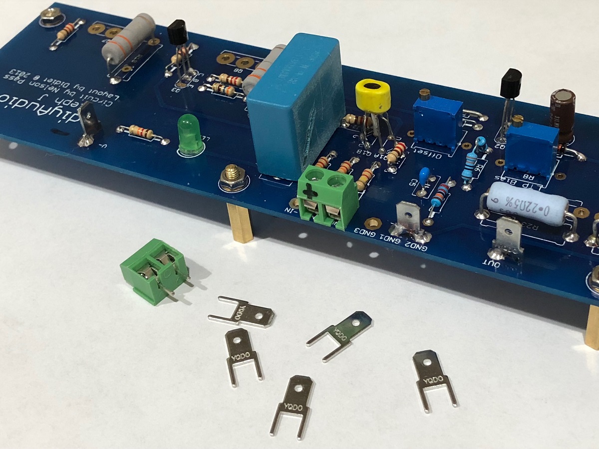
Nothing a Dremel drill press and 1.2mm drill bit can't solve... The drilled hole required scraping away the solder mask, but there is strong solder joint on bottom side of second pin of spade. Quite sturdy. 🙂
Nothing a Dremel drill press and 1.2mm drill bit can't solve... The drilled hole required scraping away the solder mask, but there is strong solder joint on bottom side of second pin of spade. Quite sturdy. 🙂
Attachments
Last edited:
Curious thing happened when drilling the PCB... as I drilled the hole for the negative rail, location on schematic is between -24V pin and R28' (12kohm) for the green LED, the LED started glowing when the bit broke through the FRP and was touching the bottom trace. It could be sustained by leaving the drill bit there. Intermittent glow but quite visible.
Is this triboelectric generation or static electricity generation? Good thing IRFP's were not mounted yet.
Is this triboelectric generation or static electricity generation? Good thing IRFP's were not mounted yet.
Last edited:
Aleph J is alive
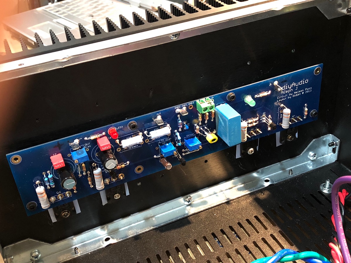
Finding qnty 8 M3 screws that are 10mm long was the biggest problem for me. Finding 8 silicone insulator pads was the next problem. The DIYA store UMS heatsink however, was superb for ease of mounting. Everything lined up perfectly. I soldered the IRFP's in with just one leg and bolted it and the PCB in place before soldering the rest in-place. I had the DVM across R18/R19 and adjusted bias current to 0.75amps per device for 1.5amps total. The bias currents in each leg matched within 1.5% (I matched the device Vgs values from a transistor tester). DC offset is about 10 to 15mV and pretty stable. Bias current is very stable. Despite my hand made P2P F6 PSU, and a semi-rats's nest of PSU wiring inside the case, the output noise measured between 0.1mV and 0.2mV on my Fluke 101 - which is very good for a speaker amp. I am listening to a few favorite test tracks right now and enjoying the sound. Overall, a very nice amp to build and easy to setup. Will let burn in for a day and then take some measurements.
Right channel installed onto heatsink:

Left channel:
Noise on output measurement with Fluke:
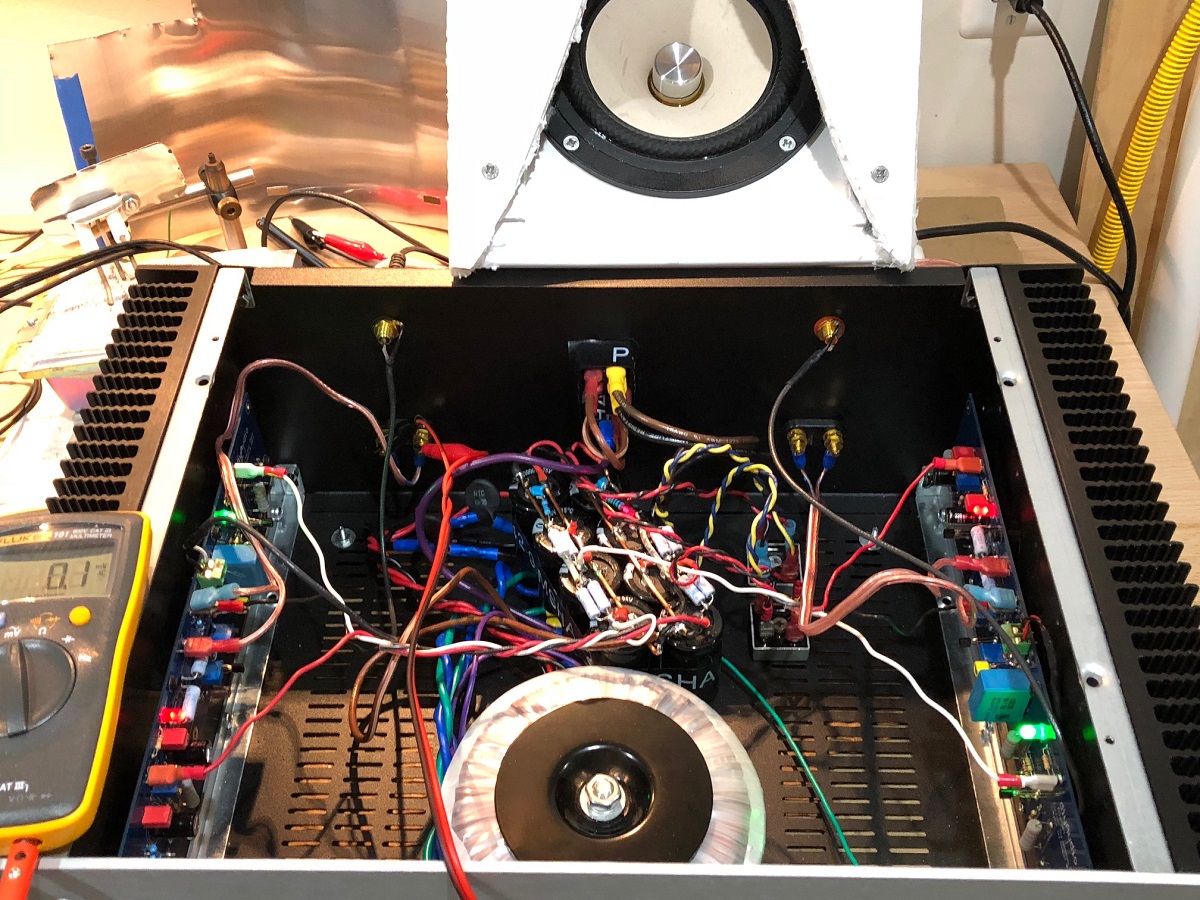
You can see the XKi with W5-2143 test speaker in the background (8ohm 90dB sensitive full range) - sounds very nice. I am driving with a Focusrite 2i4 single ended output (I soldered the -ve input to GND under the PCB). I have balanced output capability but that would require some Neutrik XLR connectors on the back panel. Maybe for another day...
Btw, my spade connectors installed on the PCB's and the 2-pin screw terminals for audio input worked like a charm.
Finding qnty 8 M3 screws that are 10mm long was the biggest problem for me. Finding 8 silicone insulator pads was the next problem. The DIYA store UMS heatsink however, was superb for ease of mounting. Everything lined up perfectly. I soldered the IRFP's in with just one leg and bolted it and the PCB in place before soldering the rest in-place. I had the DVM across R18/R19 and adjusted bias current to 0.75amps per device for 1.5amps total. The bias currents in each leg matched within 1.5% (I matched the device Vgs values from a transistor tester). DC offset is about 10 to 15mV and pretty stable. Bias current is very stable. Despite my hand made P2P F6 PSU, and a semi-rats's nest of PSU wiring inside the case, the output noise measured between 0.1mV and 0.2mV on my Fluke 101 - which is very good for a speaker amp. I am listening to a few favorite test tracks right now and enjoying the sound. Overall, a very nice amp to build and easy to setup. Will let burn in for a day and then take some measurements.
Right channel installed onto heatsink:
Left channel:
Noise on output measurement with Fluke:
You can see the XKi with W5-2143 test speaker in the background (8ohm 90dB sensitive full range) - sounds very nice. I am driving with a Focusrite 2i4 single ended output (I soldered the -ve input to GND under the PCB). I have balanced output capability but that would require some Neutrik XLR connectors on the back panel. Maybe for another day...
Btw, my spade connectors installed on the PCB's and the 2-pin screw terminals for audio input worked like a charm.
Attachments


Last edited:
Nice build! With those good noise numbers don’t fret about PSU wiring.
With all that room, try alternate C1 caps using long leads to solder out in space instead of directly to the board. I found distinct differences picking a paper in oil ultimately ��
Just trying to encourage experimentation ��
With all that room, try alternate C1 caps using long leads to solder out in space instead of directly to the board. I found distinct differences picking a paper in oil ultimately ��
Just trying to encourage experimentation ��
If I understand the theory correctly, it is because all signals must pass through that cap into the amp. The other theory I can advise on as I know this from experience is that while there are many types of construction that can be used to create a 1uF cap, they will not all behave the same exact way under different circumstances. This is how you may come to hear a difference from changing just one key capacitor in a simple amplifier.
I cannot advise exactly how and why PIO caps are different in this circumstance, I can only say I heard a consistent difference and liked the pio cap a good deal better than the high quality MKP I had originally chosen. I have nothing to sell here, it is just advice from someone who has been at this building thing for some time. I can also add a caveat that converting electricity to audio is a long series of events; you will hear the changes to the weak links first if at all. I found that C1 was a weak link; I'm just passing it on.
I cannot advise exactly how and why PIO caps are different in this circumstance, I can only say I heard a consistent difference and liked the pio cap a good deal better than the high quality MKP I had originally chosen. I have nothing to sell here, it is just advice from someone who has been at this building thing for some time. I can also add a caveat that converting electricity to audio is a long series of events; you will hear the changes to the weak links first if at all. I found that C1 was a weak link; I'm just passing it on.
I am feeding the amp with a single-ended input to the +ve input only. C1 is the -ve input and tied to GND. Will it still make a big difference?
...I suppose it does because the audio signal still has to close the circuit by flowing to GND so passes through C1 - like a shunt capacitor. I know that disconnecting the -ve from GND, you get almost no sound out.
I have some oil filled 50uF 450v motor run caps (for HVAC condensor blowers), as well as some nice Mundorf MKP's. The 1uF 450v MKP by AVX currently there should be pretty good though.
What about bypassing the C1 and make DC connection?
The signal is AC, so there has to be a connection to ground. Flow and return. All of the signal is there, so yes, it will make a big difference. Think about if it wasn't there! 🙂
The neg side of the diff amp as the bulk of the offset, which is why the input coupling cap is located there.
Remember that changing coupling caps is mainly an exercise in adding color and (hopefully) pleasant distortions. There's also a huge component in expectation bias, so obviously more expensive ones sound better. 😀
Do yourself a favor before making any changes - listen to the amp in your main system for a week or two minimum. The Aleph J is, in my opinion, the perfect DIY amp. You'll love it.
As for the coupling cap debate, or esteemed SY has published two fantastic blog entries, found here;
Why are people obsessed with coupling caps? | SYclotron Audio
Why are people obsessed with coupling caps? Part 2 | SYclotron Audio
Greetings! I am just on the cusp of ordering parts for an Aleph J build, just waiting for 2018, but I have some questions. Most interested to read your replies, one and all.
1 - I would like to add two mono stepped attenuators to my Aleph J build for volume and balance control. What impedance do I need and why (so I can learn)?
2 - Is it best to place the attenuators close to the input jacks in the back with shafts to the knobs in front to reduce noise potential or is front panel ok with wiring from input jacks sheilded and routed away from other circuits in the amp?
3 - Is there a preference as to what type of attenuator ie; shunt, ladder, or series when used in an Aleph J build?
4 - Are audio grade capacitors needed/preferred for the PSU when building the Aleph J or are Aluminum Electrolytic Capacitors an appropriate choice?
I ask as the cost is quite a bit higher for the Audio Grade.
5 - I’ve noticed some builders opt for a power transformer over the 300VA indicated in the build thread power supply. 6L6 has stated that is fine and that a larger one is also fine. I also recall reading somewhere that the 300VA is along the lines of what Papa Pass has specified. I don’t need to run the amp hot as I have very efficient (Cornscalas) speakers if that matters.
6 - Is there a preference for using the 4 x 15000 caps as opposed to using higher capacitance, say 4 x 20,000 for an Aleph J PSU build?
7 - Is there a need to change the value of the filter resistors and bleeder resistors if changing the capacitance value?
1 - I would like to add two mono stepped attenuators to my Aleph J build for volume and balance control. What impedance do I need and why (so I can learn)?
10K or 25K, it mainly depends on your source. If solid state, smaller is better
2 - Is it best to place the attenuators close to the input jacks in the back with shafts to the knobs in front to reduce noise potential or is front panel ok with wiring from input jacks shielded and routed away from other circuits in the amp?
Whatever is easier to build
3 - Is there a preference as to what type of attenuator ie; shunt, ladder, or series when used in an Aleph J build?
Not really
4 - Are audio grade capacitors needed/preferred for the PSU when building the Aleph J or are Aluminum Electrolytic Capacitors an appropriate choice?
I ask as the cost is quite a bit higher for the Audio Grade.
The "Audio Grade" are aluminum electrolytics. 🙂 It doesn't make much difference.
5 - I’ve noticed some builders opt for a power transformer over the 300VA indicated in the build thread power supply. 6L6 has stated that is fine and that a larger one is also fine. I also recall reading somewhere that the 300VA is along the lines of what Papa Pass has specified. I don’t need to run the amp hot as I have very efficient (Cornscalas) speakers if that matters.
My biggest suggestion is to buy a shielded transformer, as generally speaking, they usually have less mechanical hum. Get an Antek AS-3218 or AS-3220 (the extra volt or two won't hurt anything)
AS-3218 - 300VA 18V Transformer - AnTek Products Corp
6 - Is there a preference for using the 4 x 15000 caps as opposed to using higher capacitance, say 4 x 20,000 for an Aleph J PSU build?
Well, the normal configuration is 8 x 15,000. So that or bigger, but remember to make sure the caps still fit the PCB
These look nice -
B41252A7189M000 EPCOS / TDK | Mouser
7 - Is there a need to change the value of the filter resistors and bleeder resistors if changing the capacitance value?
No
- Home
- Amplifiers
- Pass Labs
- Aleph J illustrated build guide