KoA,
There is always concern about offset. It's the last frontier before reaching Eldorado. If it's good, and it's stable, then we have ignition.
I'd now sit on your pcb design, doodle it for a couple of weeks to be absolutely sure, and then have it made. I use ourpcb.com, their service is good and they do excellent pcbs at moderate cost, and just get four done to begin. Your production run will inevitably need changes, so don't commit too early.
Finer points of pcb layout are very hard to detect at this stage. You really have to build it now, have the thing in your hand, turning it over and inspecting it whilst building, before you have the full, 3D picture.
Thanks for your hard work, nearly there.....
Hugh
A short starting pulse approaching 1Vpk is going to eventually damage something attached to the connected headphones.
Here's something I've been thinking about, and I want to apply it to my speaker amps too;
Why not use a 3-pos switch to switch both main power and then connect your headphones? It's a small burden to have to wait a second before turning the power knob one more click 'round, and the time it takes you to turn from "ON" to the "Engage 'phones" might even be long enough for the amp to settle. Just make sure you buy a very nice switch.
Why not use a 3-pos switch to switch both main power and then connect your headphones? It's a small burden to have to wait a second before turning the power knob one more click 'round, and the time it takes you to turn from "ON" to the "Engage 'phones" might even be long enough for the amp to settle. Just make sure you buy a very nice switch.
I like that idea. The middle setting could simply be "mute".
We would have to demonstrate however that it was impossible for a human to flip the switch fast enough however.
- keantoken
We would have to demonstrate however that it was impossible for a human to flip the switch fast enough however.
- keantoken
I'll get my hands on a SPSP switch, I don't know why I didn't have a couple available here. In the meantime, I'll stare at the board layout intently. I've already got a couple things I want to iron out.
Here's an automatic way to do it (although there may be better ways).
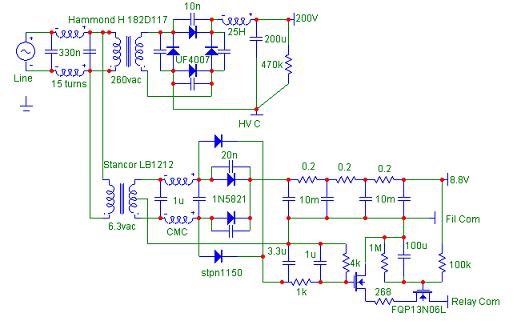
The bottom half of this figure is a filament supply and automated mute switch. The 8.8V output is just a regular filtered DC. Substitute the rail supply for this.
Now look at the two FET's. These are in series and both must be on in order to open the mute relay (not shown in this diagram). The relay coil is connected from the 8.8V output to the relay common.
The gate of one FET is powered by the two diodes that are outboard of the diodes for the 8.8V supply. It's done this way so that as soon as the power is switched off, this FET stops conducting immediately. You can change the timing by adjusting the relevant resistors and capacitor.
The other FET gate is powered by the 8.8V supply, through the 100k resistor. It must charge up the 100u cap before the FET will conduct.
So, upon turn on, the mute relay doesn't open until the amp output has had time to stabilize. But the relay closes upon power off, before the main supply droops low enough to create a transient at the output.
http://www.diyaudio.com/forums/atta...nholy-alliance-phono-amp-3a5-phono-supply.jpg
Last edited:
Yes, and maybe something a bit more complete like a 'dc protection/delay' cct with a 'mute' option - probably require something more sensitive that the usual speaker protect ccts to enable a low 100mV trigger threshold - a Maxim 'Max 4236' chip could be adapted, for example, but many other ccts, probably simpler ....
Hmm, this is getting bigger and more complicated again.....
How about driving the cans through a coupling cap? That avoids many of the protection issues and permits use of a unipolar supply.....
Hugh
How about driving the cans through a coupling cap? That avoids many of the protection issues and permits use of a unipolar supply.....
Hugh
If preferred, you can ignore this post until any current issues you guys are working on get sorted out. Or, if anybody has a quick second they could be of great help to me. I have started practicing PCB design only maybe two weeks ago. I think I am getting the hang of it. I am pretty sure I want to build this headphone amplifier, and I do see that somebody is already cooking a PCB up for it, but I want a single layer one, so I will be making my own. Here is my attempt:
http://dl.dropbox.com/u/5430178/pro...lifier/AKSA_Aspen Headphone Amplifier PCB.png
The red traces are to symbolize jumper wires on the bottom of the board. Here is the schematic that I copied in order to make the pcb, in case I screwed up somewhere:
http://dl.dropbox.com/u/5430178/pro...er/AKSA_Aspen Headphone Amplifier Circuit.png
If this is not the first priority of you guys, I understand!
PS: I just want to know if this is OK. I know it probably isn't optimal or perfect, and that is fine. I'm not expecting anybody here to walk me step by step into optimising it and wasting you're time. Then again, if you have a real quick tip to throw at me, I won't mind.
Thanks,
Aaron.
It might work but try to keep the output stage together. A pro wouldn't place parts like you have done.
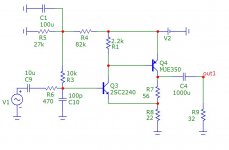
Is the first schematic in the first post meant to be built ? There are 2 things in the schematic that I do not understand which I have circled in red. Anyone knows what they represent ?
An externally hosted image should be here but it was not working when we last tested it.
V4 is a means to assess the loop gain of the amplifier (Middlebrook analysis) and I1 is current source, which could be an LM317, or a DN2540 mosfet, or a two transistor 'ring of two' .
That was a long time ago, 8 years, I'd forgotten about that! It is two stages of my NAKSA power amplifier, in fact, and because it was single ended, sounds very, very good. You may reduce the CCS 150mA down to 40mA and drive high Z cans more than 150R, saving a lot of dissipation, only 520mW total.
Hugh
I was searching for BJT headphone amplifier in this forum. This is the only other I found apart from JLH headphone amplifier. There don't seem to be as many transistor headphone amplifiers.
I was searching for BJT headphone amplifier in this forum. This is the only other I found apart from JLH headphone amplifier. There don't seem to be as many transistor headphone amplifiers.
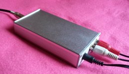
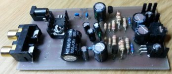
Here is another of Hugh's concoctions at about the same time 2007/8 that sounds superb. I have been using it for about 10 years now since Hugh and I searched for the most simplistic class A headphone amps.
My philosophy is the simpler a class A amp the better it sounds, my best take was three transistors, Hugh used only two. I don't even think he recalls this.
Attachments
Yes, Nico, I took a hit with a mild stroke in 2012, and I'd forgotten that you'd built both of these rudimentary HPAs!
I hope sincerely you are well and that you enjoy your Christmas and New Year!
Stay healthy, my friend,
Hugh
I hope sincerely you are well and that you enjoy your Christmas and New Year!
Stay healthy, my friend,
Hugh
Hi Hugh,
I hate getting old and lonely. Diane says that when we go out somewhere we are more out of place than two farts in a perfume bottle.
At least you still have the monster bike that is exhilarating and fun. I became a coach potato sitting day in and day out listening to music, while I could not give a rats *** what is happening around me.
Here is another of Hugh's concoctions at about the same time 2007/8 that sounds superb. I have been using it for about 10 years now since Hugh and I searched for the most simplistic class A headphone amps.
My philosophy is the simpler a class A amp the better it sounds, my best take was three transistors, Hugh used only two. I don't even think he recalls this.
Wow that looks really simple and portable too. Is this amp meant to be run from 9v or 12 v ?
Wow that looks really simple ....
Can be even more simple : Designing with FETs
"Super-Simple, Super-Fine FET Circuit"
And if you then mirror it about Gnd with PJFET and NPN, you get the F5-like topology of Nelson, or Le Monstre of Hiraga.
Cheers,
Patrick
Either, Buzzy.
It works best with BF862 and a 2SA1837, best with 12V.
Cheers,
Hugh
Yep, he's right.
- Home
- More Vendors...
- AKSA
- Aspen Headphone Amp