I'm sorry , i just see a 'broken' jpg symbol. is there a secret to viewing images here ?These were the resistors with exclamation mark. All low value types.
also. i don't know how to locate the driver transistors. I've looked at the pcb parts list and schematic but ignorance alas means I'm none the wiser !I'm sorry , i just see a 'broken' jpg symbol. is there a secret to viewing images here ?
jpg's should open with any browser. It should be visible as a small image and enlarge when clicked. It can be enlarged again by clicking the box that appears in the lower left corner.
If you are on a phone then I don't know details but I'm guessing it should work.
I don't do mobiles
If you are on a phone then I don't know details but I'm guessing it should work.
I don't do mobiles
also. i don't know how to locate the driver transistors. I've looked at the pcb parts list and schematic but ignorance alas means I'm none the wiser !
You need a readable diagram in from of you.
Here is the same image saved as a .png file. See if that works. Lets link it as well.
http://www.diyaudio.com/forums/attachment.php?attachmentid=650531&stc=1&d=1512931486
Attachments
*goes upstairs to turn on pc that is possibly of interest to local museum* 🙂jpg's should open with any browser. It should be visible as a small image and enlarge when clicked. It can be enlarged again by clicking the box that appears in the lower left corner.
If you are on a phone then I don't know details but I'm guessing it should work.
I don't do mobiles
aha ! it works now . Thank you so much I'll check them all tomorrow evening. that's very kind of you , much appreciated !These were the resistors with exclamation mark. All low value types.
You're right unfortunately, for the cyrus one issue 07 they no longer fitted a bias adjustment. I wonder if i could add that back as I'm guessing the circuit board didn't change much. If not I think you were suggesting a work-around using preset components?A dual 0.22 ohm can be replaced by two singles. They are just wired in series with the junction being what would be the middle leg of the original dual. The CPC ones in the link should be fine.
There is no need for any matched transistors in this amp.
The bias could be a real issue and so I would suggest ordering a 1k and 2k preset to play about with.
The drivers are the pair of transistors directly feeding the outputs, the MJE243/253 pair. BD139/140 should be fine for these. Other commonly used parts for these would be MJE340 and MJE350.
right, so, the outputs are all npn. But the drivers are one npn and one pnp ? I looked at each of the pairs you suggested. They seem to have different specs in regards to hFE , is it important to pick a device with the right hFE or is the gain decided by the circuit and all i need are drivers with sufficient headroom to cope ?You're right unfortunately, for the cyrus one issue 07 they no longer fitted a bias adjustment. I wonder if i could add that back as I'm guessing the circuit board didn't change much. If not I think you were suggesting a work-around using preset components?
Don't for get the bulb limiter if you miss adjust the bais as you can blow the output devices very quickly with out it.
Two ways to set bais..1 current, where you place the meter in current mode and place the probes in the + rail with the fuse removed or the 2 one is read the millivolts across the .22 ohm resistors.
Now say your reading is 15mv with bulb limiter pluged in and your need to reset it once you remove the limiter as it will be higher!
Good luck there
cheers. at this stage I'm enlisting the help of a neighbour who recently built a pass f5t and I'm certain i saw lighbulbs and multiple meters and biasing going on.Don't for get the bulb limiter if you miss adjust the bais as you can blow the output devices very quickly with out it.
Two ways to set bais..1 current, where you place the meter in current mode and place the probes in the + rail with the fuse removed or the 2 one is read the millivolts across the .22 ohm resistors.
Now say your reading is 15mv with bulb limiter pluged in and your need to reset it once you remove the limiter as it will be higher!
Good luck there
thanks for your continued help. In return I'll do everything possible to educate myself to minimise the questions . cheers!
You're right unfortunately, for the cyrus one issue 07 they no longer fitted a bias adjustment. I wonder if i could add that back as I'm guessing the circuit board didn't change much. If not I think you were suggesting a work-around using preset components?
Very easy to do, essentially snipping one resistor out and tagging the preset in its place.
right, so, the outputs are all npn. But the drivers are one npn and one pnp ? I looked at each of the pairs you suggested. They seem to have different specs in regards to hFE , is it important to pick a device with the right hFE or is the gain decided by the circuit and all i need are drivers with sufficient headroom to cope ?
The overall gain of the circuit is determined by the feedback network, the individual gains of the transistors having no practical effect once the feedback loop is closed. That's one of the beauties of feedback, it means the circuit is reproducible with a wide variety of different semiconductor parameters.
brilliant thank you !Very easy to do, essentially snipping one resistor out and tagging the preset in its place.
The overall gain of the circuit is determined by the feedback network, the individual gains of the transistors having no practical effect once the feedback loop is closed. That's one of the beauties of feedback, it means the circuit is reproducible with a wide variety of different semiconductor parameters.
Hi, the service manual seems to suggest that the bias can be adjusted to reduce the voltage (measured at R107A & R108A) by increasing the value of R81 to 180R or if the voltage is too low, by connecting a 220R cross R81. Does that sound plausible ?I have heard of the MJE3055T being used for replacement output transistors on the Cyrus. Cheap and readily available (CPC). BD139/BD140 for the drivers.
0.22 ohm/3watt resistors,
http://cpc.farnell.com/multicomp/mcknp03sj022ka19/resistor-wirewound-0r22-5-3ws/dp/RE07407
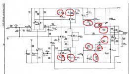
You need to check the value of all the resistors marked with an exclamation mark in the faulty channel. These are low value resistors and can be checked in circuit initially. If you don't see the reading expected then try reversing the meter leads. If it still looks wrong then lift one end and check. The shorted outputs/drivers may skew the result of some of these so remove the faulty transistors first.
The Cyrus appears to have non adjustable bias and this will be a possible issue using different non original semiconductors.
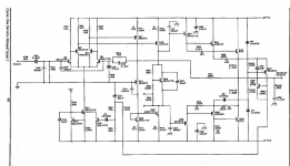
You may have to change the value of R63, a 680 ohm (hard to make the ref number out), perhaps even replacing it with a preset to give continuously variable adjustment.
Also you must use a bulb tester when working on this as it will save damage should anything go amiss.
The bias current is calculated from the volt drop across either of the 0.22 ohm resistors (always with no speaker attached).
The bias adjustment is done by what is called a vbe multiplier and altering the conduction of the transistor. The network of R81 and R83 would be replaced by a preset giving total control.
The numbers in the manual are so poor (blurred) that its difficult to quote which transistor it is. I think its Q39.
The trouble with fixed resistors are that you have no fine control and in fact very few amplifiers use fixed.
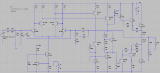
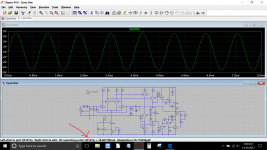
Here is the Cyrus redrawn and put into a simulation (it all works correctly) but I'm not 100% sure I've got all the reference numbers correct.
The bias adjustment is done by what is called a vbe multiplier and altering the conduction of the transistor. The network of R81 and R83 would be replaced by a preset giving total control.
The numbers in the manual are so poor (blurred) that its difficult to quote which transistor it is. I think its Q39.
The trouble with fixed resistors are that you have no fine control and in fact very few amplifiers use fixed.
Here is the Cyrus redrawn and put into a simulation (it all works correctly) but I'm not 100% sure I've got all the reference numbers correct.
Attachments
Thanks 🙂 and yes, very handy. I couldn't do that on a mobile.
I was trying to find something on vbe multipliers and expected a zillion hits, but no......
Class AB amplifiers
Rubber diode - Wikipedia
And I have never come across the term 'rubber diode' before. How weird is that.
I was trying to find something on vbe multipliers and expected a zillion hits, but no......
Class AB amplifiers
Rubber diode - Wikipedia
And I have never come across the term 'rubber diode' before. How weird is that.
I'll be very careful with autocorrect when i google it. hoping to get time to test those resistors tonight after work (I'm tempted to replace them all tbh, though disturbing the tracks on the board unnecessarily might be unwise)Thanks 🙂 and yes, very handy. I couldn't do that on a mobile.
I was trying to find something on vbe multipliers and expected a zillion hits, but no......
Class AB amplifiers
Rubber diode - Wikipedia
And I have never come across the term 'rubber diode' before. How weird is that.
- Home
- Amplifiers
- Solid State
- Cyrus 1 output transistor question. push-pull?