Ok I am willing to try a series parallel made from qnty 4 x 12k SMT metal thick film resistors. I think I can solder them up like Lego blocks.
Let's see if it measures the same or better than a single 12k carbon film through hole.
Thick film resistors were always a noisy choice whenever I used them in an audio circuit.. But they are warm sounding though, probably more second harmonics...
Last edited:
Noise increases as the square root of resistance. Every resistor is ultimately already a series/parallel resistor array. So chopping the array up into 4 sections in SMD packages will not change the relationship. The 4 resistors will have the same noise as a single resistor of the equivalent value.
There's another noise to consider with thick film resistors, beyond thermal noise. That's excess noise and it manifests as predominantly LF noise related to the voltage dropped across the part. The smaller sized resistors are worst at it (0603 thick film is best avoided when there's significant voltage drop).
Noise increases as the square root of resistance. Every resistor is ultimately already a series/parallel resistor array. So chopping the array up into 4 sections in SMD packages will not change the relationship. The 4 resistors will have the same noise as a single resistor of the equivalent value.
I suspected that the fundamental principle of infinitesimal math would be violated if the above were not true. So really, the difference would be more power handling and less effect on tempco.
This article may be interesting and informative to this subject..
Selecting resistors for preamp, amplifier and other audio applications
Selecting resistors for preamp, amplifier and other high-end audio applications | EE Times
Selecting resistors for preamp, amplifier and other audio applications
Selecting resistors for preamp, amplifier and other high-end audio applications | EE Times
Thick Film SMT Series Parallel Test
Well, this is very interesting indeed. Pretty much conclusively says it isn't a tempco issue but the intrinsic material used that changes the distortion profile.
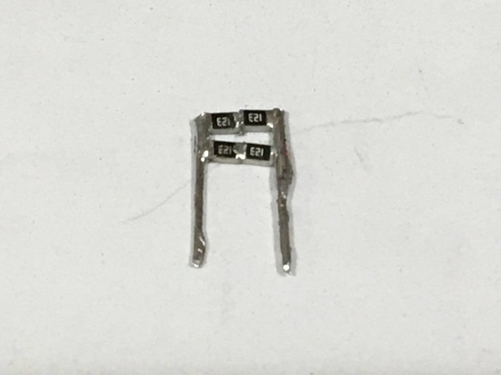
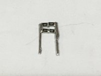
Here is my little 12kohm series parallel resistor made with qnty 4 x 12kohm 0805 thick film resistors (no name brand). The assembly measures 12.07kohm with Fluke 115:
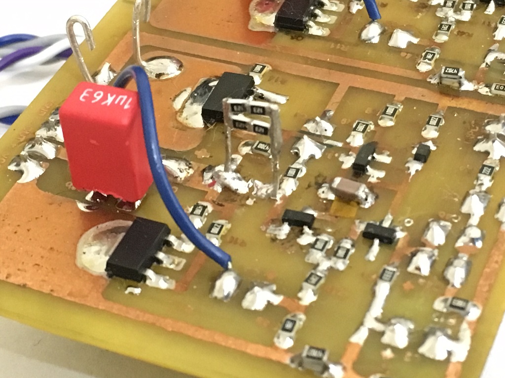
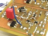
Here it is installed on the preamp:
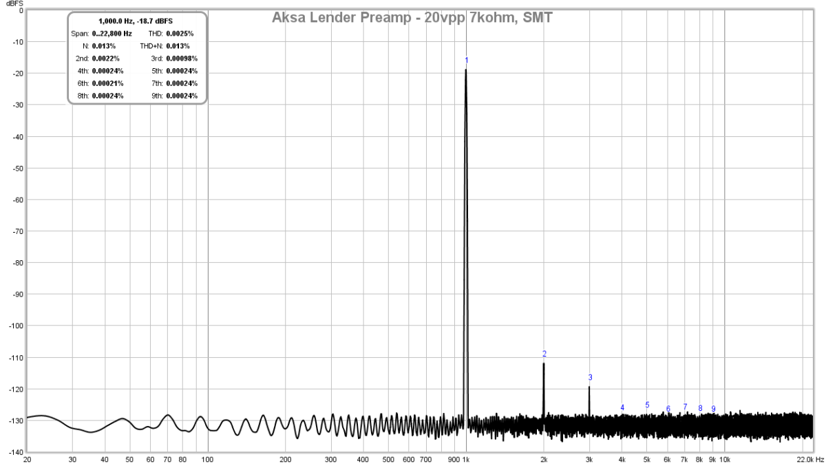
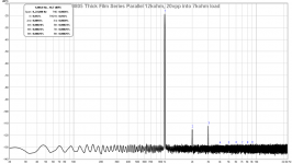
Here is the FFT for 20vpp into 7kohm load, note that the third harmonic is now back where it was even with one of these resistors. Now technically 0.5w capable since each is 1/8w, and it is in mid air for good cooling:

In contrast to earlier measured FFT at same condition for 12k carbon film:
Who would of thunk?
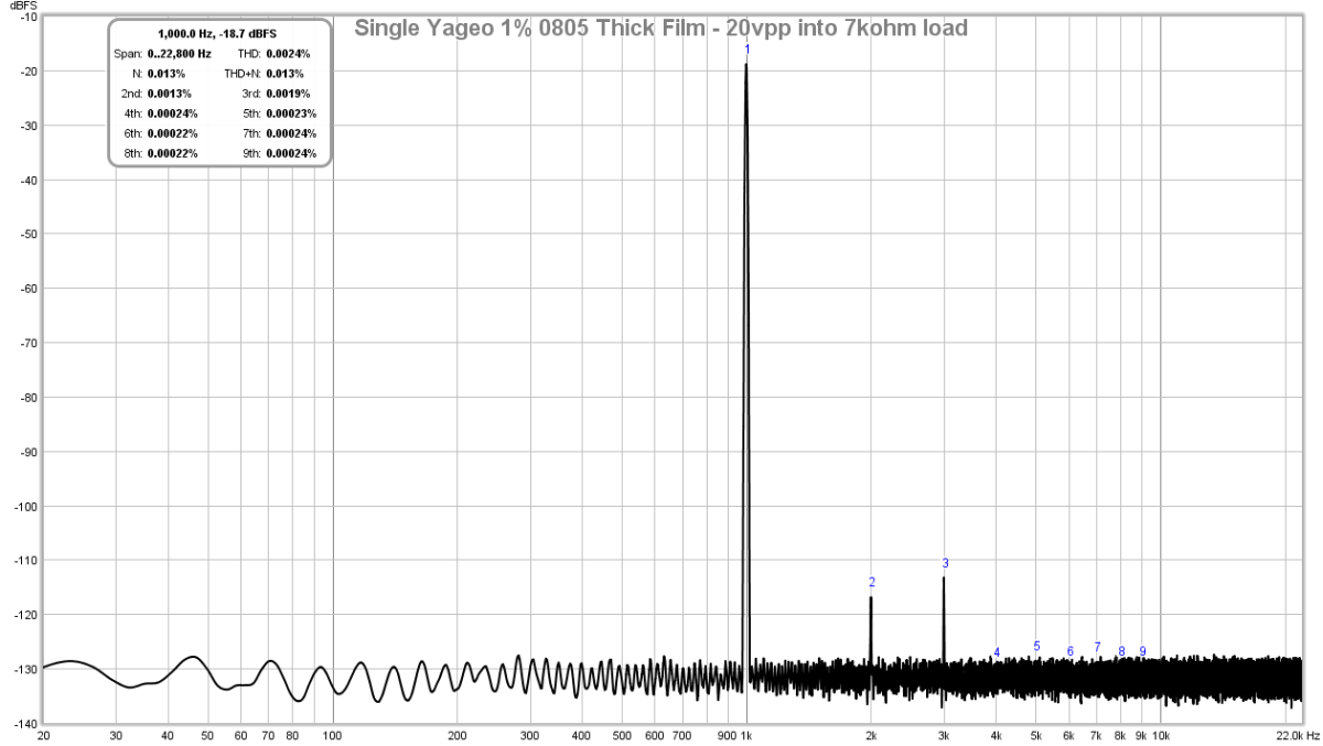
Edit: so I had to check to see if it was because these SMT thick films were of dubious quality. So I installed a single Yageo 0805 thick film 1% 12kohm resistor (from Digikey) and I get this for the FFT:
Well, this is very interesting indeed. Pretty much conclusively says it isn't a tempco issue but the intrinsic material used that changes the distortion profile.
Here is my little 12kohm series parallel resistor made with qnty 4 x 12kohm 0805 thick film resistors (no name brand). The assembly measures 12.07kohm with Fluke 115:
Here it is installed on the preamp:
Here is the FFT for 20vpp into 7kohm load, note that the third harmonic is now back where it was even with one of these resistors. Now technically 0.5w capable since each is 1/8w, and it is in mid air for good cooling:
In contrast to earlier measured FFT at same condition for 12k carbon film:
Who would of thunk?
Edit: so I had to check to see if it was because these SMT thick films were of dubious quality. So I installed a single Yageo 0805 thick film 1% 12kohm resistor (from Digikey) and I get this for the FFT:
Attachments

Last edited:
Here is my little 12kohm series parallel resistor made with qnty 4 x 12kohm 0805 thick film resistors (no name brand).
...
Here is the FFT for 20vpp into 7kohm load, note that the third harmonic is now back where it was even with one of these resistors. Now technically 0.5w capable since each is 1/8w, and it is in mid air for good cooling:
Is this the same resistor you referred to as 'metal film' in this post here:
Here is FFT with metal film SMT:
Or a different one ?
(Thick film is not usually referred to as metal film, because thick film composition is usually an oxide, whereas thin film is almost universally metal)
It would be of interest to make a 2s2p combination of the carbon film and compare.
Last edited:
My mistake in terminology then, what I thought was metal thin film was probably thick film (as it was cheap). I just repeated the test with thick film of known provenance (see above) and get the same result.
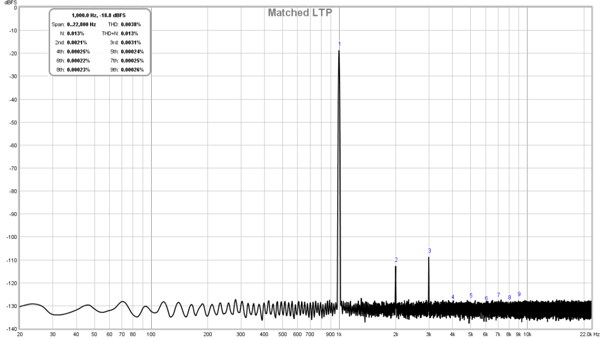
Edit: so I repeat the experiment, now with 12.4kohm 1% metal thin film axial through-hole resistors (actually a 5.6k + 6.8k in series). These are the cheap blue ones from China. Again, 20vpp into 7kohm load:
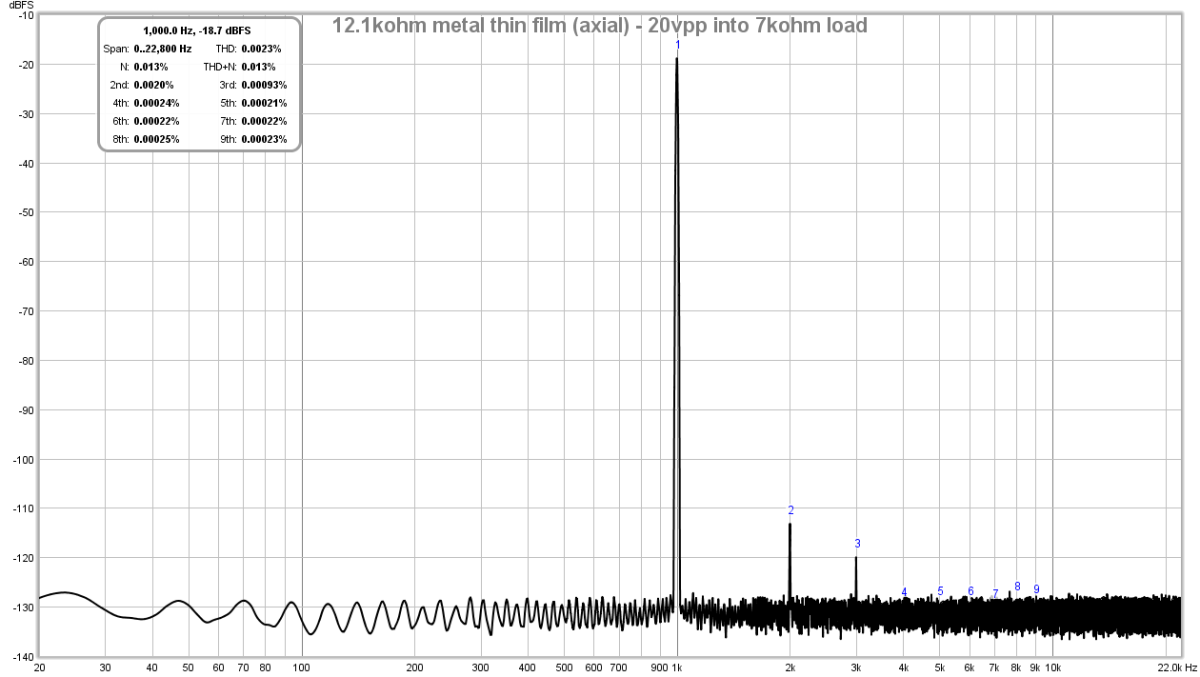
Well, it measures pretty well. So I guess the problem is the "Thick Film" resistor.
Edit: so I repeat the experiment, now with 12.4kohm 1% metal thin film axial through-hole resistors (actually a 5.6k + 6.8k in series). These are the cheap blue ones from China. Again, 20vpp into 7kohm load:
Well, it measures pretty well. So I guess the problem is the "Thick Film" resistor.
Attachments
Last edited:
Well, it measures pretty well. So I guess the problem is the "Thick Film" resistor.
Agreed, the evidence definitely singles out the thick film resistors as being generative of the taller 3rd harmonic, and does not support the hypothesis that the carbon resistor was performing a cancellation effect.
I think this has been the case in most cases where the thick film's voltage coefficient has been encountered on other topics here. It would be interesting to see what would happen if the thick film were on the ground leg of the feedback - as the 'generative' effect would be reversed if it were a voltage coefficient issue, i.e: possibly resulting in a cancellation.
Last edited:
I currently have thick film SMT on ground leg of feedback (between FB and shunt cap to ground). I have already tried changing it and it makes little difference due to fact that most of voltage drop occurs on the 12k and not the 1k value.
Here IMS version data set to check: schematics, part list, implentation, PCB details.
Silkscreen after check.
Second standard FR4 version after check.
Data set for both version will available for DIY community.
Starting part list for mainboard.
JP
Hi JP,
I had a look at the files and all looks good. Thanks for making this for the community! Will this be on metal substrate?
Cheers,
X
Please check (four eyes principle).
JP
Hi JP,
I looked these files over and they look fine as well - although I am not completely familiar with your inpmementation of the input selector switch and CLC filter so assume you have that covered. It looks like you are making a snap-away segmented board. Won't board houses complain and charge a board price for each little sub board? That could get expensive. Alternatively, a single flat board without breakaways and fully connected without jacks and cables would also be nice and simplify assembly. That's more work though so onlyif you feel you have time. You did a great job though - very professional full-featured PCB motherboard. Impressive.
Thanks,
X
Thank you X for checking.
I´m still working on "SMD hater" THT version (PANASONIC FC capacitors 63VDC); I confirm three version:
- IMS SMD (needs skills and tools)
- standard FR4 SMD
- THT
Needs some small modification on main board for all versions but I´ve to check component height then I want to use 1U HIFI2000 enclosure.
Thinking finishing with production datas for all version latest thursday so it´s possible to order PCB´s before Christmas.
JP
Attachments

hey man what software are you using to measure the THD?
My measurement rig consists of a Focusrite (either Solo, 2i2 or 2i4, all 2nd gen and all seem to measure similarly - same ADC I assume) USB audio interface and a Windows PC running REW Software. Use the RTA mode with spectrum plot option, Blackman-Harris 7 filter, and use the built-in generator to produce the sine wave. It's actually a pretty high purity one if you do a loop-back test you will see.
X,
Thanks for doing the 4 resistor tests. Very interesting results. I am still surprised that resistance material drives a harmonic problem, but your tests are clear. I learn something new everyday.
Jac
Thanks for doing the 4 resistor tests. Very interesting results. I am still surprised that resistance material drives a harmonic problem, but your tests are clear. I learn something new everyday.
Jac
This three version would be available for customer (still verifying mainboard).
JP
JP
Attachments
-
 AKSA-LENDER-PRE-SMD_PCB-TOP.png763 KB · Views: 252
 -
 AKSA-LENDER-PRE-SMD_PBA-TOP.png896.1 KB · Views: 275
 -
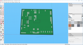
 AKSA-LENDER-PRE-IMS_PCB-TOP.png599 KB · Views: 547
 -
 AKSA-LENDER-PRE-IMS_PBA-TOP.png929.5 KB · Views: 561
 -
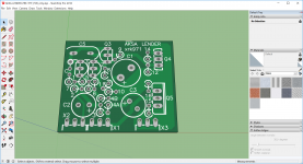 AKSA-LENDER-PRE-THT_PCB-TOP.png688.8 KB · Views: 582
 -
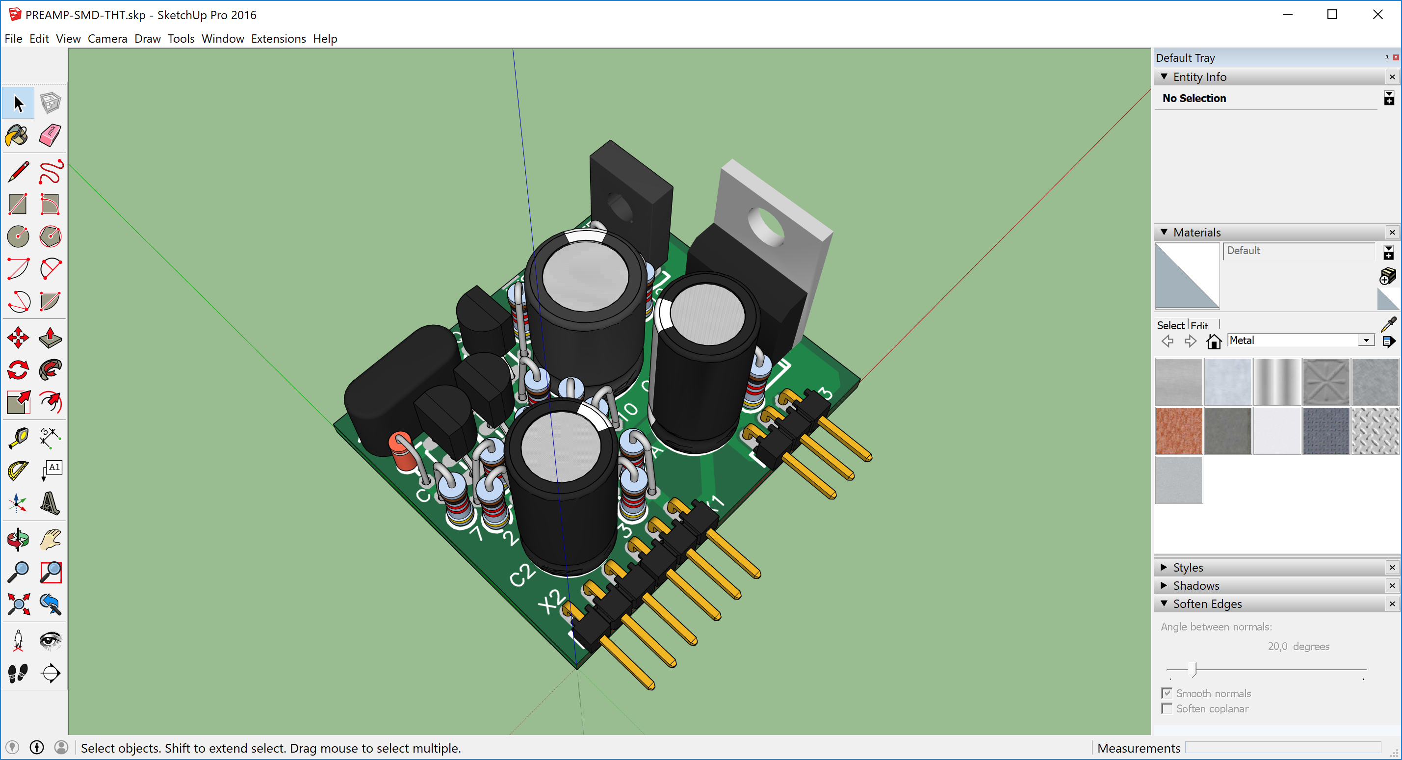
 AKSA-LENDER-PRE-THT_PBA-TOP.png687.3 KB · Views: 8,855
 -
 AKSA-LENDER-PRE-SMD_PCB-BOT.png459.5 KB · Views: 228
This three version would be available for customer (still verifying mainboard).
JP
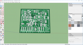
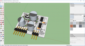
Man Sketch up does a very good job...how can i learn??
JP,
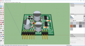
You are a master of sketchup. It's not easy - so my hat's off to you for making these so quickly.
The through-hole version is neat in that one can attach external heatsinks to the TO220 devices and change a few resistors as I suggested and turn it into a headphone amp core module with 80mA bias current and 24v Vcc.
Or, one could use the external heatsink through hole version souped up for 70vpp output. The 90vpp version has a slightly different compensation scheme so is not universal.
One could even mount the parts with pins bent 90 and sticking up to allow TO220's to be screwed to case wall or heatsink flat surface.
I am looking forward to ordering some of these boards now though.
Last edited:
- Home
- Source & Line
- Analog Line Level
- AKSA's Lender Preamp with 40Vpp Output