Here is something to chew on:
http://www.barthelectronics.com/pdf...1 Voltage Coefficient Products_Pulse Page.pdf
2 mechanisms can cause the carbon comp resistor to create odd harmonics. Thermal tempco and voltage coefficient. Resistance decreases at fast voltage peaks due to voltage coefficient, but it increases for slow voltage peaks due to tempco. In that paper it was found 1/2W carbon comp resistors have less distortion overall.
Distortion from voltage coefficient will be the same regardless of frequency, but distortion from tempco will not. So I suggest you do tests between metal film and carbon comp at 50Hz and 10KHz to see if the effect of carbon comp is the same across the spectrum.
Harmonics don't just add, they subtract as well. Since carbon comp resistance decreases with voltage (positive 3rd harmonic), then it must be countering an opposite distortion from the amp or from your test devices (negative 3rd harmonic). That is assuming it is due to voltage coefficient and not tempco...
Last edited:
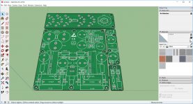

Main PCB only, silkscreen finshed.
JP
Very talented Sir, how in the world did you get it all done so quick 🙂
Here is something to chew on:
http://www.barthelectronics.com/pdf...1 Voltage Coefficient Products_Pulse Page.pdf
2 mechanisms can cause the carbon comp resistor to create odd harmonics. Thermal tempco and voltage coefficient. Resistance decreases at fast voltage peaks due to voltage coefficient, but it increases for slow voltage peaks due to tempco. In that paper it was found 1/2W carbon comp resistors have less distortion overall.
Distortion from voltage coefficient will be the same regardless of frequency, but distortion from tempco will not. So I suggest you do tests between metal film and carbon comp at 50Hz and 10KHz to see if the effect of carbon comp is the same across the spectrum.
Harmonics don't just add, they subtract as well. Since carbon comp resistance decreases with voltage (positive 3rd harmonic), then it must be countering an opposite distortion from the amp or from your test devices (negative 3rd harmonic). That is assuming it is due to voltage coefficient and not tempco...
Thanks for showing us this paper, Kean. I bet it is more an effect due to temperature coef. Those 1/8th watt 0805 are puny. Thinking about what AC power is dissipated is enlightening. For 20vpp that's 7vrms and for a 10k resistor that's 5mW. I suppose 5mW is not insubstantial but well under he 125mW rating. Perhaps it's the pulsed nature. Peak power is different ?
If you look at what I did here on the HyQu, I spread the load over 7 resistors even though they were never anywhere near their rating.

Last edited:
Oops, I totally misinterpreted what you posted. I thought you had tried a carbon comp resistor. I didn't realize you were using tiny SMD resistors. Thermal distortion is a much more likely explanation then.
In that case, you can look at the resistor section of this powerpoint by Bruce Hofer from AP:
By Bruce Hofer, Chairman & Co-Founder, Audio Precision - Hosted by Bonis Audio - 2013 June
In that case, you can look at the resistor section of this powerpoint by Bruce Hofer from AP:
By Bruce Hofer, Chairman & Co-Founder, Audio Precision - Hosted by Bonis Audio - 2013 June
Hi X,
Maybe fancy round cylinders resistors?
JP
Haha, yes! Especially on the feedback one 🙂
Oops, I totally misinterpreted what you posted. I thought you had tried a carbon comp resistor. I didn't realize you were using tiny SMD resistors. Thermal distortion is a much more likely explanation then.
In that case, you can look at the resistor section of this powerpoint by Bruce Hofer from AP:
By Bruce Hofer, Chairman & Co-Founder, Audio Precision - Hosted by Bonis Audio - 2013 June
Thanks for that Kean. So looks like the recommendation is that 1206 size metal THIN FILM 5ppm or 10ppm stability is ideal for low distortion audio circuits. So for signal path and feedback caps, I will have to look at buying a good set to have. For feedback applications: 680R, 820R, 1k, 4k7, 6k8, 10k, 22k should be enough to have on hand for this special purpose.
Yikes, these are pricey. Vishay 1-TNPW1206100KBYEA 0.1% 10ppm 1206 10k thin film is $1ea!
TNPW1206100KBYEA Vishay | Mouser
But I bet it would have fixed my distortion problem, worth every penny. 😀
Jumping into this conversation way late.
Your FFT results between metal and carbon film are very interesting. You also mentioned using an axial on a SMT location. Of course that is possible, but I have had good luck with Vishay MELF carbon film of the CMA/CMB series. I agree that its not always easy to find the value you are looking for, but they work well if available.
This may have been mentioned, but for reducing distortion from resistors, 4 resistors in a parallel - series arrangement (all the same value as a single resistor) provide a 12 dB reduction in distortion. The paper below discusses the theory to some extent.
http://www.nanovolt.ch/resources/low_distortion_oscillators/pdf/low_distortion_oscillator_design.pdf
Or four in parallel of 4x the value? I now know that a single 0805 is. It sufficient for a feedback.
Hi X,
Fascinating work on the resistor distortion issue. Thank you, and to others contributing.
I have had good results using Stackpole thin films. Here is a suitable resistor from Panasonic:
P6.8KQCT-ND
It's 1210, 1/4 watt, and 0.1%. This should suit the bill and cost around 60c each, 50c in 10+!
Hugh
Fascinating work on the resistor distortion issue. Thank you, and to others contributing.
I have had good results using Stackpole thin films. Here is a suitable resistor from Panasonic:
P6.8KQCT-ND
It's 1210, 1/4 watt, and 0.1%. This should suit the bill and cost around 60c each, 50c in 10+!
Hugh
Last edited:

Sorry, I didn't explain that very well. The article I linked explains the math. Look in "Main Oscillator Loop" subsection "Passive Components".
Let say that you have a 1k feedback resistor and you want to reduce distortion. If you use 4 of the same 1k resistor with 2 of each in series and the 2 series strings in parallel, you get a combined resistor network of 1k. The voltage on each resistor is half due to the series connection and that results in distortion that is only 1/4 or -12 dB of the single resistor.
You also get a resistor network that has 4 time the power specification of the single resistor, but that isn't needed here.
Hi Guys!
I personaly do not believe that H3 at -80dB is able to spoil the sound in anyway, even the go(l)denears cannot hear -80dB of H3 vs fundamental, this phenomena is rather due to interracting of H3 and other distortion in feedback loop creating accidental "hf noise" together with highly nonlinear feedback resistor.
I personaly do not believe that H3 at -80dB is able to spoil the sound in anyway, even the go(l)denears cannot hear -80dB of H3 vs fundamental, this phenomena is rather due to interracting of H3 and other distortion in feedback loop creating accidental "hf noise" together with highly nonlinear feedback resistor.
Sorry, I didn't explain that very well. The article I linked explains the math. Look in "Main Oscillator Loop" subsection "Passive Components".
Let say that you have a 1k feedback resistor and you want to reduce distortion. If you use 4 of the same 1k resistor with 2 of each in series and the 2 series strings in parallel, you get a combined resistor network of 1k. The voltage on each resistor is half due to the series connection and that results in distortion that is only 1/4 or -12 dB of the single resistor.
You also get a resistor network that has 4 time the power specification of the single resistor, but that isn't needed here.
Yes this is clearer explanation, I did read that part but I see no where that says the music distortion will be reduced or whatever AC voltage signal will be reduced, What I took away with me was the "passive components", the resistors self distortions will be reduced not the AC signal.
some heavy reading for sure, maybe you can explain it to use better but thats what i got from the article.
Lawrence
Ok I am willing to try a series parallel made from qnty 4 x 12k SMT metal thick film resistors. I think I can solder them up like Lego blocks.
Let's see if it measures the same or better than a single 12k carbon film through hole.
Let's see if it measures the same or better than a single 12k carbon film through hole.
Yes this is clearer explanation, I did read that part but I see no where that says the music distortion will be reduced or whatever AC voltage signal will be reduced, What I took away with me was the "passive components", the resistors self distortions will be reduced not the AC signal.
some heavy reading for sure, maybe you can explain it to use better but thats what i got from the article.
Lawrence
Hi Lawrence,
I totally agree the it's heavy reading. In truth, that's why I put the link instead of trying explain it myself (Sure to screw it up). The tough read is probably made worse by the fact that the author isn't just working for low distortion, but also a way of measuring very low levels of distortion.
Without getting into high level math, my understanding is that the distortion added to a signal when it passes through a resistor is a function of the voltage drop across the resistor (lower voltage is lower distortion). By the way, for other reasons, this is also true of current noise in resistors.
(https://dcc.ligo.org/public/0002/T0900200/001/current_noise.pdf)
When you do the parallel-series combination of 4 resistors, the circuit sees the same voltage drop and current as a single resistor, but the individual resistors in the parallel-series network are operating at half the voltage and half the current of the single resistor. So, there is lower distortion going with lower voltage. The author doesn't go into detail, but apparently these resistor distortions are uncorrelated, so don't add together. The result is lower distortion from the resistor network.
Normally, this wouldn't be an issue because resistor distortion would be below the distortion of other components in the circuit an inaudible. In this case, the FFT has shown that the resistor is involved, so these kind of interesting approaches are worth checking out.
Jac
Ok I am willing to try a series parallel made from qnty 4 x 12k SMT metal thick film resistors. I think I can solder them up like Lego blocks.
Let's see if it measures the same or better than a single 12k carbon film through hole.
That would be great! I don't know how it will come out, but it is an interesting experiment.
One thing to look for in the measurements would be whether the low frequency of the SMT resistors is noisier than the carbon film through hole. There isn't a lot of data available, but data there is suggests that the thick film material will have higher current noise (noticeable at low frequencies) than the carbon film. Carbon film doesn't appear to have as low current noise as the best metal films, but is lower than the thick film data available.
Jac
I have not read the paper yet. But it seems what you are saying is that series parallel has less distortion since voltage drop is less through each resistor is odd. There is something that doesn't seem right. It would seem that this violates a fundamental law of conservation of energy. The noise from a lower drop in voltage but having four more resistors would seem like it would be a wash. I see power handling and tempco effects being different but not simply because of voltage drop. If it is tempco related, having parallel divided currents through multiple resistors would reduce the distortion since less heating in each resistor.
Voltage coefficient is a separate phenomenon from thermal distortion. They are both present and add together. Less voltage drop per resistor means less total resistance change due to voltage coefficient.
Thermal distortion is related to voltage only in that it's hard to make a case for temperature being independent from voltage. But no, tempco is not a voltage coefficient.
Thermal distortion is related to voltage only in that it's hard to make a case for temperature being independent from voltage. But no, tempco is not a voltage coefficient.
I see power handling and tempco effects being different but not simply because of voltage drop.it seems what you are saying is that series parallel has less distortion since voltage drop is less through each resistor is odd. There is something that doesn't seem right. It would seem that this violates a fundamental law of conservation of energy.
I am in no way an expert here. Your statement above is what I understand the author of the paper to be saying. There is some more explanation in the paper, but unfortunately he also relies on things like, "it can be shown that" which don't help us understand it.
Hopefully, someone will correct me on this. What I understand is that a correlated noise or distortion would be linearly related to the input signal. In the case of correlated distortion, the distortions of the 4 resistors would add together. However, nonlinear and random noise and distortion are considered uncorrelated to the input and they don't add together. As I understand it, the 4 resistors at lower voltage add the distortion of a single resistor, not the sum of all 4. In other words, it looks like something for nothing.
What is nice about you trying this test is that you have a case where you are able to measure the distortion effects of a specific resistor. In many circuits, the resistor distortion would be something like -130 dB and immeasurable. That way, even though we don't understand the theory completely, we can see if it works. Who knows, it might even make metal film SMTs feasible.
Jac
- Home
- Source & Line
- Analog Line Level
- AKSA's Lender Preamp with 40Vpp Output