There are plenty of posts already on this forum on how small smt resistors can be unsuitable for feedback due to thermal modulation. jcx has posted about it a long time ago and suggested using at least 1206 resistors as feedback resistors for opamps (and that was on low voltage rails).
I wonder if the reduction in H3 really has anything to do with carbon film. It might well rather be linked to the difference in size and power handling.
I wonder if the reduction in H3 really has anything to do with carbon film. It might well rather be linked to the difference in size and power handling.
Thanks for pointing that out. I did not think of it before but can try maybe four in parallel to see if that's the case.
Try carbon composition resistors in the experiment.Thanks for pointing that out. I did not think of it before but can try maybe four in parallel to see if that's the case.
I have experimented with resistor types in the FB shunt and series resistor positions and got a range of results.
The FB shunt cap is sonically critically imortant IME also.
Adding 'ideal' smaller values across the shunt electro cap counter intuitively cleans and extends the highs, also improves bass 'solidness' and mids/vocals clarity.
The experiment is in seeing how noise sources interact and modulate and subjectively counter or augment input signal embedded noise.
Dan.
I think carbon composition would sound smoother. But I have heard they are prone to instability issues and don't keep a steady value over time. This could be a problem in the feedback loop as gain stability is important for channel balance. I should try adding a film bypass across the shunt capacitor though.
As I understand modern carbon comp resistors have reasonable encapsulation as long as you don't destroy it. Some datasheets will give you the results of the moisture sensitivity test. If you're still worried you can spray them with conformal coat.
There is one webpage where a guy measured all his carbon comp resistors, put them in an oven and then measured them again. He kept the ones that measured the same before and after.
There is one webpage where a guy measured all his carbon comp resistors, put them in an oven and then measured them again. He kept the ones that measured the same before and after.
I looked into the carbon comp thing more. Old Allen-Bradley carbon comps often still read within 1%. It seems no one makes them like that any more. Modern carbon comps are designed to be be tolerant of moisture and usually come back to their original value when baked or soldered.
The one thing they are excellent for is their enormous pulse tolerance. Good for snubbers. If I interpret the failure data right, they seem to slightly prefer running hot. See page 3:
https://www.mouser.com/ds/2/303/RCC-3-17.19-1139652.pdf
Average lifetime 410 to 960 thousand hours or at least 47 years at 90-95% humidity. None of the 10% batch failed so it looks like the failure was simply to stay within 5% tolerance.
So carbon comps do drift in value, but they don't necessarily drift more than 5% unless really neglected.
Aksa Lender Preamp driving a MoFo
So I had an hour to throw together the MoFo amp (unity gain single transistor MOSFET follower amp). I did not have a 50mH inductor on hand so substituted the inductor with a power resistor for temporary test to get sound. My MoFo is using am IRFP240 and 24v SMPS followed by a CRC made with 22mF and 0.22R resistors. The resistive load is not ideal as it limits peak power due to lack of reactive load from the inductor. However, I am running it at 1.5amps bias so it is solid for playing a few watts into high efficiency speakers. The Aksa Lender preamp can drive it hard and it can get loud. Sounds very nice on test speaker (XKi fitted with Tang Band W5-2143):
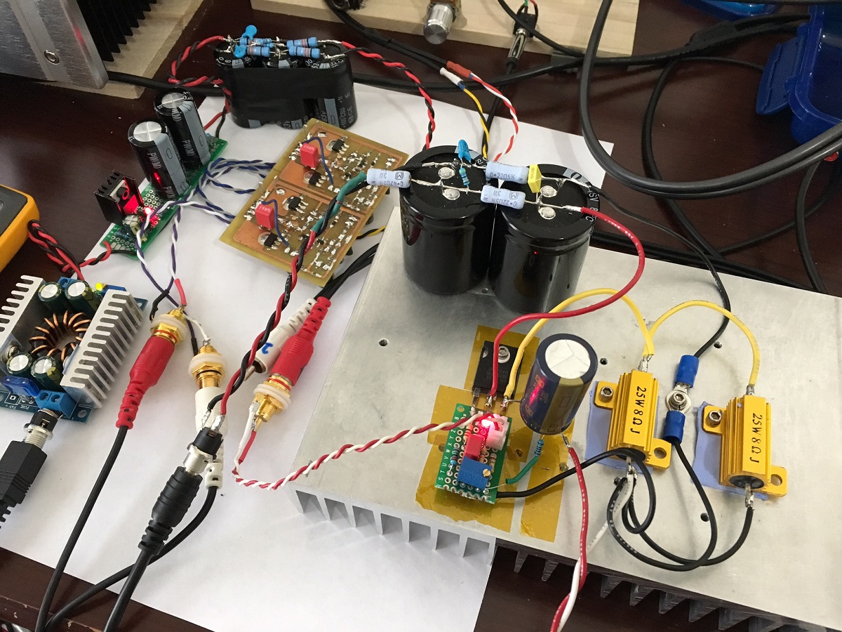
So I had an hour to throw together the MoFo amp (unity gain single transistor MOSFET follower amp). I did not have a 50mH inductor on hand so substituted the inductor with a power resistor for temporary test to get sound. My MoFo is using am IRFP240 and 24v SMPS followed by a CRC made with 22mF and 0.22R resistors. The resistive load is not ideal as it limits peak power due to lack of reactive load from the inductor. However, I am running it at 1.5amps bias so it is solid for playing a few watts into high efficiency speakers. The Aksa Lender preamp can drive it hard and it can get loud. Sounds very nice on test speaker (XKi fitted with Tang Band W5-2143):
Attachments

Last edited:

I looked into the carbon comp thing more. Old Allen-Bradley carbon comps often still read within 1%. It seems no one makes them like that any more. Modern carbon comps are designed to be be tolerant of moisture and usually come back to their original value when baked or soldered.
The one thing they are excellent for is their enormous pulse tolerance. Good for snubbers. If I interpret the failure data right, they seem to slightly prefer running hot. See page 3:
https://www.mouser.com/ds/2/303/RCC-3-17.19-1139652.pdf
Average lifetime 410 to 960 thousand hours or at least 47 years at 90-95% humidity. None of the 10% batch failed so it looks like the failure was simply to stay within 5% tolerance.
So carbon comps do drift in value, but they don't necessarily drift more than 5% unless really neglected.
Thanks for checking this out. I will order some with my next order of stuff.
@xrk971
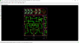
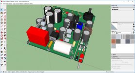
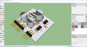
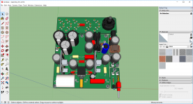
Should look like that as preamplifier powered by SMPS.
Someone to check (also last schematics post) so that I can finish this job.
No intention for GB (only a few boards for me and friends) so I´ll put all the datas online (EAGLE binaries, manufacturing datas).
Have a nice weekend.
JP
Should look like that as preamplifier powered by SMPS.
Someone to check (also last schematics post) so that I can finish this job.
No intention for GB (only a few boards for me and friends) so I´ll put all the datas online (EAGLE binaries, manufacturing datas).
Have a nice weekend.
JP
Attachments
Very nice JP! So this is a multi input selector knob and there is a CLC to clean up before the cap Mx? The power should be very clean then. Can you please post the BOM so I can get a sense of the parts needed like pots, switches, etc.
Thanks,
X
Thanks,
X
So I had an hour to throw together the MoFo amp (unity gain single transistor MOSFET follower amp). I did not have a 50mH inductor on hand so substituted the inductor with a power resistor for temporary test to get sound. My MoFo is using am IRFP240 and 24v SMPS followed by a CRC made with 22mF and 0.22R resistors. The resistive load is not ideal as it limits peak power due to lack of reactive load from the inductor. However, I am running it at 1.5amps bias so it is solid for playing a few watts into high efficiency speakers. The Aksa Lender preamp can drive it hard and it can get loud. Sounds very nice on test speaker (XKi fitted with Tang Band W5-2143):

Here are some measurements of the Aksa Lender Preamp driving a MoFo at 2vpp as a headphone amp. It sounds very very nice. Lush, deep depp bass. No sibillance or harshness. Can listen to it all day.
HV version with 70v peak-peak into 10kohms 0.0077% THD
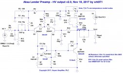
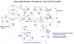
I rejiggered a few components and adjusted several resistors for a HV version of this amp that puts a nice clean 0.0077%THD 70vpp signal into a 10kohm load. LTP current is maintained at 2.5mA but now using MMBT5401 for higher voltage. BSP129 can handle 240v Vds and of course DZT5401 can handle -150v Vce. Gain is about 20dB and with 100v rail we can get a very nice harmonic distortion profile at a swinging 70vpp.
Schematic HV version 2.0:
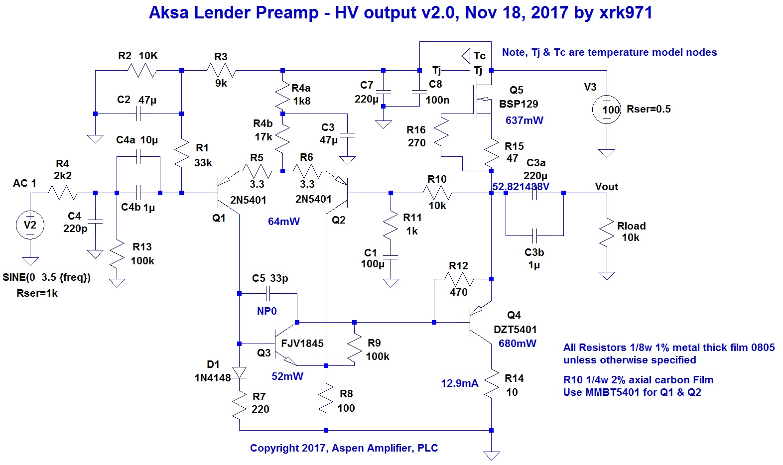
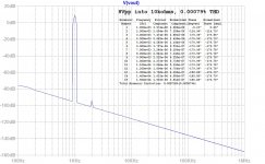
FFT for 70.0v peak-peak into 10kohm load:
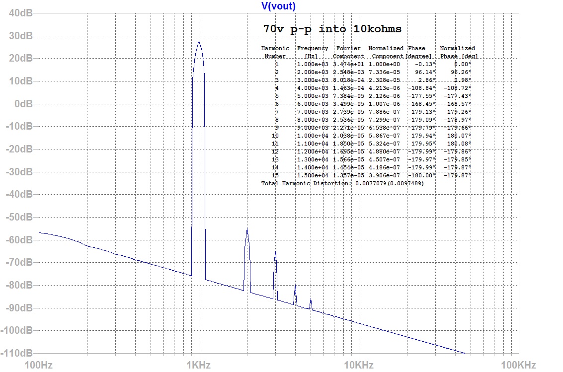
70vpp driving a unity gain output stage is good for 75Wrms into 8ohms.
I rejiggered a few components and adjusted several resistors for a HV version of this amp that puts a nice clean 0.0077%THD 70vpp signal into a 10kohm load. LTP current is maintained at 2.5mA but now using MMBT5401 for higher voltage. BSP129 can handle 240v Vds and of course DZT5401 can handle -150v Vce. Gain is about 20dB and with 100v rail we can get a very nice harmonic distortion profile at a swinging 70vpp.
Schematic HV version 2.0:
FFT for 70.0v peak-peak into 10kohm load:
70vpp driving a unity gain output stage is good for 75Wrms into 8ohms.
Attachments
Last edited:
@xrk971
Should look like that as preamplifier powered by SMPS.
Someone to check (also last schematics post) so that I can finish this job.
No intention for GB (only a few boards for me and friends) so I´ll put all the datas online (EAGLE binaries, manufacturing datas).
Have a nice weekend.
JP
Hi JP,
You are very energetic and prodigious in your layout output. Since this preamp is an open forum design, I hope that you will make either the Gerbers or Eagle files for your layouts available freely in this thread. It sounds like you are planning to do this, but just confirming.
Thanks,
X
Here IMS version data set to check: schematics, part list, implentation, PCB details.
Silkscreen after check.
Second standard FR4 version after check.
Data set for both version will available for DIY community.
Starting part list for mainboard.
JP
Silkscreen after check.
Second standard FR4 version after check.
Data set for both version will available for DIY community.
Starting part list for mainboard.
JP
Attachments
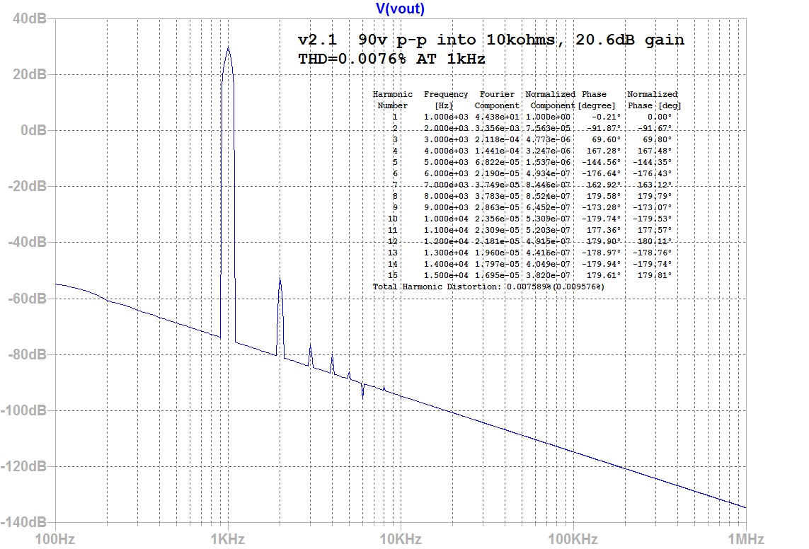
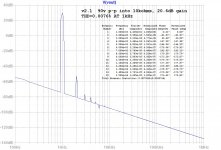
HV v2.1 90vpp into 10kohms 0.0076% THD
With Hugh's guidance, I was able to tweak the circuit for some more bias in the LTP and the VAS stage. Switching to beefier TO220 parts with real heatsinks as we are dissipating 3w ea now. But performance into 10kohms with 90v peak-peak is better than before. More compensation was needed at high voltages.
Schematic:
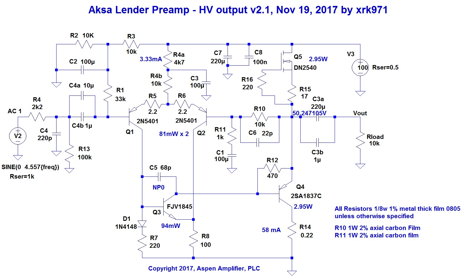
FFT for 90Vpp into 10kohms:
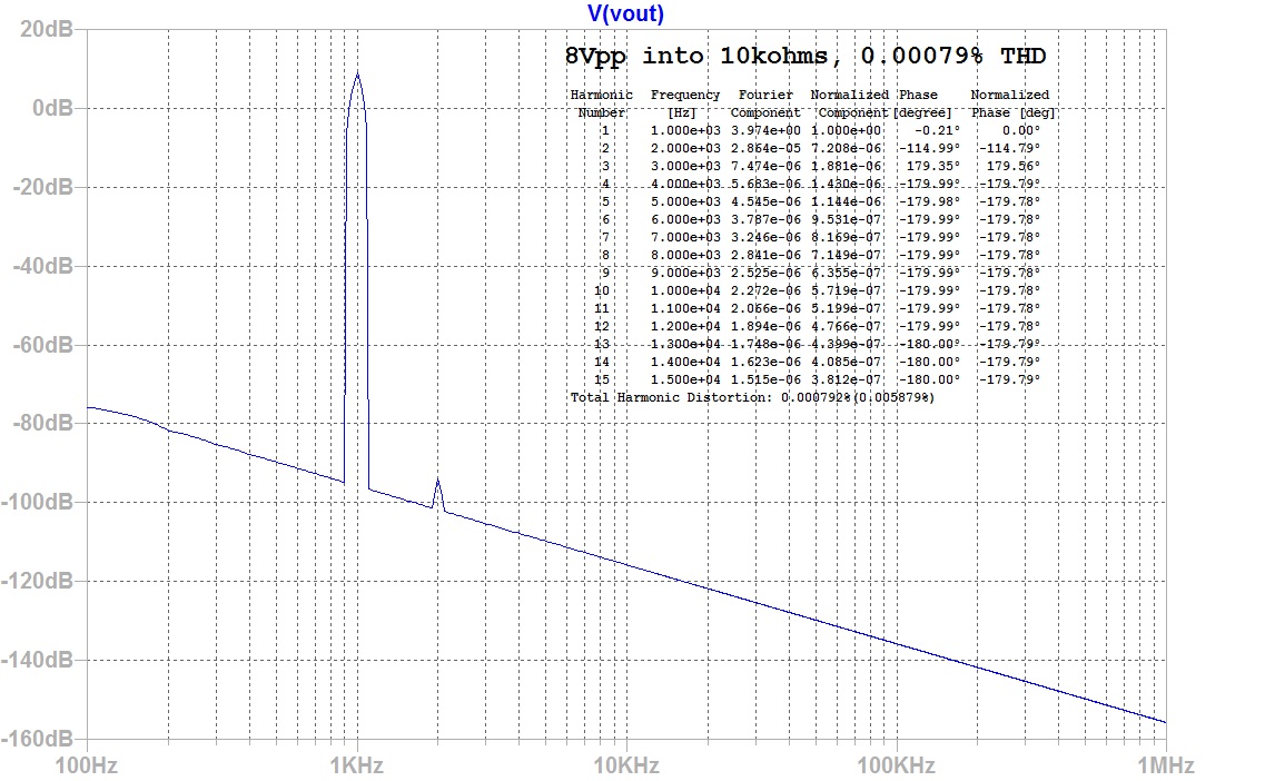
Here is 8vpp into 10kohms, 0.00079% THD:
With Hugh's guidance, I was able to tweak the circuit for some more bias in the LTP and the VAS stage. Switching to beefier TO220 parts with real heatsinks as we are dissipating 3w ea now. But performance into 10kohms with 90v peak-peak is better than before. More compensation was needed at high voltages.
Schematic:
FFT for 90Vpp into 10kohms:
Here is 8vpp into 10kohms, 0.00079% THD:
Attachments
Last edited:
- Home
- Source & Line
- Analog Line Level
- AKSA's Lender Preamp with 40Vpp Output