Hi Ale,
I remembered your observation that on one setup the 4P1L driving 4P1L had some not so nice tizziness while not apparent on another which you suspected may have something to do with H3. From the cited reference, there is another mechanism where H2 of the one stage interacting with H2 from the next stage giving rise to different sonic impression. Perhaps it is useful to also take a note of the H2 phase at the speaker terminal before listening after some change to the system.
I remembered your observation that on one setup the 4P1L driving 4P1L had some not so nice tizziness while not apparent on another which you suspected may have something to do with H3. From the cited reference, there is another mechanism where H2 of the one stage interacting with H2 from the next stage giving rise to different sonic impression. Perhaps it is useful to also take a note of the H2 phase at the speaker terminal before listening after some change to the system.
Hi Ale,
I remembered your observation that on one setup the 4P1L driving 4P1L had some not so nice tizziness while not apparent on another which you suspected may have something to do with H3. From the cited reference, there is another mechanism where H2 of the one stage interacting with H2 from the next stage giving rise to different sonic impression. Perhaps it is useful to also take a note of the H2 phase at the speaker terminal before listening after some change to the system.
That might have been one of the incarnations of my system - 4P1L into PSE 4P1L. But there might be some other reasons for the rather "hard" sounding treble in that case. Since then I've upgraded the filament supplies with a substantial choke input supply to the regs used for filament bias. That smoothed out the sound for a start.
There isn't a dedicated 2p29l preamp thread so I'll just post it here: A neat way of attaching the tubes to the front of the chassis. Identifikacia : Spojovaci prostředky
Attachments
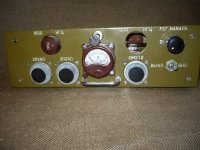
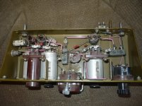
There isn't a dedicated 2p29l preamp thread so I'll just post it here: A neat way of attaching the tubes to the front of the chassis. Identifikacia : Spojovaci prostředky
Ah - so that's what the deep sockets are for and why the tubes have a handle on the end to pull them in and out. I get it now.
The other relevant thing is that this offers extra shielding to the tube. Handy for cutting down on hum.
.
Last edited:
I think I could grow to like such a design with the tubes upfront with the small handles and all. It looks different and cool. Then again, I've been accused of being a hipster so who knows...
It looks different and cool. Then again, I've been accused of being a hipster so who knows...
Hipster or SteamPunk-er 😀 Kindest regards
Steampunk Amplifier: 10 Steps (with Pictures)
Attachments
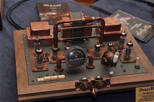
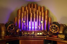
Ha-ha! Great designs, but perhaps a bit too much. Even for me. You probably need to be some kind of opera phantom in a submarine to make them fit your living quarters.
Ok, I have build a line-stage as stated before with a 4p1l, a LL1692 in Differential pair and a CCS in the tail. It is directly fed by may Es9018 DAC. Pretty straight forward.
As I made recently some experences with the g3-connection of the EL34, I thought: let's look into different configurations of the 4p1l incl. "screen-mode"/Mesh.
i knew that the 4p1l is a different beast in many ways than the el34, but I took my son's 20x microscope and looked into the tube and its grids. They are in elipses around each other, g3 is MASSIVE and very tightly woven compared to a el34. So, different behavior to be expected.
These are first of all only utracer measurement with a 4.2V heater and cathode at mid-tap from a NOS tube, but with average emission/parameters, there are stronger ones out there..
I used two different bias points to understand some sensitivities:
Anode (V) g3 Va Vg Ia kohm gm (mA/V) mu W
150 Cathode 150 -9,5 29,31 1,73 5,27 9/101% 4,4
n.c. cathode 150 -9,5 18,78 2,62 3,42 9/100% 2,8
cathode cathode 150 -9,5 18,27 2,55 3,56 9/101% 2,7
n.c. 150 150 -9,5 29,99 1,9 4,33 9/100% 4,5
cathode 150 150 -9,5 28,55 1,87 4,31 8/89% 4,3
150 150 150 -9,5 38,67 1,48 5,75 8/94% 5,8
150 cathode 150 -13 13,14 2,28 3,95 9/100% 2,0
n.c. Cathode 150 -13 8,51 3,66 2,45 9/100% 1,3
cathode cathode 150 -13 7,66 3,62 2,44 9/98% 1,1
n.c. 150 150 -13 16,38 2,27 3,54 8/89% 2,5
cathode 150 150 -13 14,87 2,32 3,43 8/89% 2,2
150 150 150 -13 20,45 1,77 4,63 8/91% 3,1
So, Hv is always 150, g2 is always at 150V. You ready it like
(example: first row):
- Anode: 150V
- G3: at Cathode
- Va: (always 150, needed to calc Watt)
- Vg: -9.5V or -13V (the two scenarios)
- Ia, Kohm, gm, mu the different measurement results.
(second row🙂
- Anode: not conected at all
- g3: at cathode...etcetc
(third row)
- Anode: At cathode connected
- G3. At cathode connected....yadi, yadi, yadi
Some big surprises here:
- First of all, when biasing the 4p1l with 150V/30mA overall dissipation is fine with 4.4W, but if I measure without anode attached, I get a hefty 2.8W on g2 which is far out of its specs of 1.5W. My guestimate (maybe wrong): This is the emission we always get from g2 (as well if anode is active): So g2 /bias needs a complete different attention !!! I need to measure this in a working amp I guess...
- g3 in Mesh-Mode has a huge contribution !!! We can achieve nearly parameters like with Anode active !!!and knowing that g3 is build like a tank (from the microscope), I guess this can become a very interesting Mesh-Mode.
Maybe not so surprising:
- With Anode and G2 and G3 all together: Highest Emission etc.
- With Anode at Cathode, and G2+G3 at as Anodes: A bit less emission / good parameters than if g2+G3 are together and Anode not connected to anything.
Next weekend I will build and listen...
ps. can someone help me to get this table in a readable form into the forum ? Even spaces are omitted, when I try to edit this manually.
Last edited:
Hi Ale,
So, I continued my work now more on the pratical side and build a complete new base (heavy+on rubber feet), used NOS Russian sockets this time and build in switches for anode and g3 which allow me to try different combinations.
Here are my impressions:
- G3 at cathode gives a certain "sound". Quiet musical. And that is the sound I am used to at the moment as the sockets I used sofar (from Kevin C.) have this as the build in default.
- G3 at the anode makes the muscial sound veil go away and you have a more honest, but as well less romantic presentation. A bit more clearer as well and better, deeper room. But I need to compare these two modes a bit more to really conclude.
- Anode connected to cathode, so that G2 and G3 become the new Anode: Another step into refinement. More and finer details. But subjectively less loud, less dynamic, less body and soul in the music. Not sure, that I will become a fan of this. I need to gain more experience.
I believe we are here now at a point where you can hear any detail regarding component selection etc. Especially when g2 and g3 become the anode and alle the current go through the two grid-stopper (100ohm) I had still in the game.
Some good news on this mode: You can raise at 150V the total current through the tube to 24mA and g2 will stay in its 1.5W limit. Even going above 1.5W to 1.8W did not make anything red. Ale, so no need to stay at 10mA...
I guess my questions / projects for the next weekend are:
- What is the best sounding g2/g3-stopper ? I used Mills NS(non-inductive)-WW, but I have these under suspicion that they make up for the metallic sound going from g3 to cathode to MEsh, where the sound of these become more and more prominent as more and mor current goes through them.
- Ale, if I saw it right you omitted the grid resistor in MESH completely, right ?
- Shall I try to not connect the anode at all ?
- Put an aquarium onto the tubes (seriously a nano cube)
The disappointing news: I can still clap my hands and get music from the speaker. Not, its not Alexa, its the 4p1l. Even with the heavy sockets, the 5mm Aluminium-plate they are attached to and the rubber-subchassis: These guys are really microphonic like hell. So, I will finish my tests on the right setup and than move on to the 2p29l and the 10y/801A is waiting to challenge those as well...
Best Regards
Frank
Last edited:
Love it
Hi Frank
I've always connected g2+g3+anode directly. If I read you correctly, there isn't a very good reason to change this?
I've always connected g2+g3+anode directly. If I read you correctly, there isn't a very good reason to change this?
Hmm...I believe most people use between 100-300ohm to prevent oscillations...but if you had no issues with connecting directly: I will try this for sure alternatively, the ferrites Rod Coleman suggested might be as well a try...but next weekend I will follow your route...and use BBC Europe on LW to see if there are any oscillations...
Hmm...I believe most people use between 100-300ohm to prevent oscillations...but if you had no issues with connecting directly...
I don't know if I have oscillation issues - haven't measured very high frequencies. Maybe I should put some grid stoppers in. This is just for the output stage, PSE, that I'm talking about.
4P1L using Grid as Anode.
Hi Blitz,
I have built a version of Ale's 4P1L line stage, this is in the normal anode mode, but am about to alter this & run it in what Ale calls screen mode, I do feel that the actual valve is not as coloured (less romantic) than some others. Does this add more timbre & depth to the sound? I am using Ale's Gyrator Boards & find them to be excellent, are You using Transformer Output?
Hi all,
I am building my 2P29L, not extactly 4P1L. I am using ALe circuit on his website. Can I ask if I put a 100k pot at input, do L need to adjust the grid leak resistor R9 49k value?
Thanks
Daniel
I am building my 2P29L, not extactly 4P1L. I am using ALe circuit on his website. Can I ask if I put a 100k pot at input, do L need to adjust the grid leak resistor R9 49k value?
Thanks
Daniel
Ok, I continue my work on the 4p1l...
So, as I said: You clap your hands and your system claps for you...the microphony of the 4p1l is really bad. Lowering the heater voltage makes it a bit better, but not really stops it. And it sounds not as good imho.
So, I was looking for the ultimate tube damper...and found it:
IMG 1527 — imgbb.com
A heavy piece of brass, I estimate nearly a lb per piece from your friendly plumber store...You wrap the tube in white teflon tape, which makes the brass fit tightly and which as well gives a little vibration dampening...but most importantly now we have MASS around the tube and it is 95% quiet...the rest will be killed in the v2 version of this marvelous damper ("The Blitz Damper" all rights reserved 😉 ).
On the listening impression, the short story is:
- getting rid of the resistors was a big step in naturalness, better dynamics etc.
- running the 4p1l with 22mA/194V in both, Mesh with g2 and g3 as anodes vs. both of them plus anode: I believe Mesh gives you more inside without any downside. Regarding Plate dissipation: At 24mA/150V I measured g2 within 1.5W limit. Someone with a lot of experience (Kees) who is using pentodes for the last 10 years this way, told me: As the anode is not used and stays cold, the dissipation at g2 can be 25% higher...which gives us 4.5W dissipattion limit for g2+g3 together. This sounds still very powerful.
Last edited:
What I found out as well: It is now so tranparent that it makes anything you do with your PSU EXTREMELY audible. I had a solid stated CCS and a OD3 in (like Lynn Olson in the Karna): Something odd, unnatural, like a hand-brake was still on. Changed this to a LCLC with amorphous chokes (the marvelous stuff from AE50): WOOOOOOOW, it CAN sing !
Last edited:
- Home
- Amplifiers
- Tubes / Valves
- 4P1L DHT Line Stage