I just converted my 4p1l pre to 2p29l. I reduced the current to 15mA as at 20mA when I measured the voltages it seemed to be considerably over 2w dissipation. My initial thoughts on the sound is very positive, no microphonics at all which is a real positive. Bass is excellent but treble maybe a little forward. I will give it some time before deciding what is best.
One problem I have is that to get my Coleman v4 regs to work I changed the sense resistor to 6.9 ohms. This gives me the correct adjustable range. But the preamp now has a slight hum as compared to when it was using 4p1l. Should I have changed anything else on the heater regulator to make it work properly at 120mA? Or is the issue elsewhere?
Cheers
Ian
I've absolutely no idea except to speculate whether it's to do with grounding, since the 2P29L has a conductive aluminium case, plus it has a couple of pins which could also be connected to ground. Anyone know the best grounding method for the 2P29L?
One problem I have is that to get my Coleman v4 regs to work I changed the sense resistor to 6.9 ohms. This gives me the correct adjustable range. But the preamp now has a slight hum as compared to when it was using 4p1l. Should I have changed anything else on the heater regulator to make it work properly at 120mA? Or is the issue elsewhere?
Cheers
Ian
For best results with the 2П29Л (Ifil = 105-140)mA, setting R1 = 8.2Ω (2W wirewound - no film resistors!) will be optimal for stability.
With V4 regulators, R8 may have to be re-optimised if you have changed the supply voltage: R8=1K 7-12V; 3.3K up to 20V.
The supply should be about 7V for best results, too. Once fully optimised, there should be no hum from the filament current, at all.
I changed the heater regs to be exactly as Rod suggested. I earthed everything, then tried rebuilding the HT PSU and a more elaborate gyrator on the anode.
On the test bench it measures perfectly for voltage and current. But it hums, whatever I do, even tried different 2P29L's. I think I will revert back to 4P1L and give it some more thought.
I should also add that exactly the same chassis and general wiring worked faultlessly with the 4P1l so I dont think its an earth loop or anything silly.
Cheers
Ian
Hi Ian, how did you wire the 2P29L? Like my diagram?
I had no hum issues, in fact it was dead quiet.
If you can share your schematic and some pictures we may see what could be the issue
Have you tried different 2P29L valves?
Thanks
Ale
I had no hum issues, in fact it was dead quiet.
If you can share your schematic and some pictures we may see what could be the issue
Have you tried different 2P29L valves?
Thanks
Ale
Hi Ale,
I have HT of 264 V that goes into a DN2540 CCS (set at 40mA) this feeds to 100V VR tubes. The shunt regulated voltage is actually 215V. The output of the VR tubes has a 56nF Russian Teflon cap. The HT then goes to two gyrators. The gyrators are your design with 2X LND150 and a DN2540 on top of a J310. The current on the gyrators is set at 15mA each. The voltage on the anodes is 142.7V. The Coleman regs were set to 120mA filament current. The filament bias resistor is 60R so about 7V until HT is applied and then goes us to 8V. The input voltage to the Coleman regs is 16V per channel.
All these numbers seem in line with what has been shown, which is both pleasing but irritating as it makes finding the fault more difficult.
I have tried two sets of 2P29L, both sets the same.
Also grid stoppers on G2 and G3 are 330R and 1K on G1.
I have now done a complete rebuild ith better quality Loctal sockets and moved the G1 to ground 47K resistor much closer to the socket pins. I think this helps but still there is an issue. I will persevere.
Any ideas?
Cheers
Ian
As Ale says, exactly how are you wiring the sockets? All pins including the centre one? Do you have a diagram?
. . . The output of the VR tubes has a 56nF Russian Teflon cap . . . Any ideas?
Cheers
Ian
That could be too much capacitance for the VR tubes leading to oscillation depending upon the load. Try a smaller cap (.01uf) or no cap at all and see if it affects the hum.
---Gary
No need for VR with a gyrator,
Waste of regulation stage.
If you post pictures of your build we may be able to help...
Waste of regulation stage.
If you post pictures of your build we may be able to help...
UPDATE on the balanced issues described above: The transformer is the http://www.lundahl.se/wp-content/uploads/datasheets/1692A.pdf
in AM-PP version.
The dramatic hizing of the windings and the loud white noise happen only when wiring this transformer according to the data sheet above in Alt. M !!!
I got it working in 1.75+1.75:1, 1.75+1.75:2, 1.75+1.75:2+2, but not in Alt M, but in taking the normal "4" connection scheme, so all windings linear in series and conect earth to the middle tap.
I have no idea why this transformer freaks out in the suggested winding scheme of the manufacturer. Especially given that it is the PP-version made for this job. Maybe 60mA in the primary is too much ? But the SE-scheme work flawless with that current...
This is only a reference point...next I will compare it with the Monolith ITA-02 and finally than Ale's boards in balanced...
ps...Per Lundahl just send me an email and suggested to giv the secondary windings a 10k resistor to work into...will try this and see if Alt M. will work with this...sofar the resistor they worked into was only the 330k resistor grid to ground of the power.amp...
Last edited:
Hi!
Did you do some measurements as I advised you by email? Instead of blindly trying different wirings it would be wiser to try to find the root cause. Something must be different between the way you wire everything up. A transformer by itself does not oscillate. If you draw detailed schematics which show every connection for an alternative which works and which doesn't it might be possible to help. Maybe you have a weird ground loop in one of them?
But again, pulling out the scope and tracing the source of the oscillations is far more helpful.
BR
Thomas
Hi Thomas,
Well....The advise: "Take out your Osciand figure it out and btw per definition it cant be the transformer"...is a bit too generic, sorry and does not reflect my observations:
I took a simple and logical approach which was: Narrow the issue down by comparing what works and what does not.
So, starting with a setting which works. The normal ways of wiring the secondaries like for an SE-Output: Works. Dead-Silent. Wonderful music.
THAN
Using this setting (SE-"4") with CT as ground for balanced: WORKS. BAlanced Input into my Power amp works, so it is nothing wrong with the input stage of the power amp.
That for me was a big AHA. Why does this way of wiring it up works and Alt M. not ?
THE ONLY THING changed was the internal connection of the transformer towars Alt M., nothing else. And than it starts to freak out.
I will try now the 10k resistor across the secondary as suggested by Per to see if this calms it down.
I have drawn the extremely simple circuit above. There are not too much to be messed up...especially given that the circuit is dead silent in SE-output-config of the transformer...
Just to be sure: I will raise the grid resistor and include a cathode resistor between the CCS (Kevin Carter's current sink which should be free from any oscillations...) and the cathodes (100ohm), just to be sure that no oscillations are there and current is a bit better balanced (measured a difference of only 0.5mA between the two 4p1L !!!, so almost no big deal for a PP-transformers.
Maybe I will lower the current to something like 15mA instead of 28 mA per tube and see if this makes a difference in Alt M.
Just trying to help...
Changing the loading resistor will not cause a difference between wildly oscillating or quietness. The signal must come from somewhere and that cannot be the transformer itself. Just measuring the signal at various stages of your circuit would give much better insight into whats going on. Based on your description above it is not clear to me what exactly the difference is.
Thomas
I finally got my 2P29L line stage to run silently. After a lot of faffing on, the problem is in the Coleman regs. I haven't gone over them properly to pin it down and correct it but when I substituted them out for some DHT filament supplies UI had from Andrew Lehane (described on Audio Talk) I was greeted with silence.
Immediate impressions of the 2P29L line stage is very positive. Very detailed top end but not edgy and deep powerful bass. The lack of microphonics is simply astonishing.
When I get time I will investigate the Coleman regs.
Cheers
Ian
Immediate impressions of the 2P29L line stage is very positive. Very detailed top end but not edgy and deep powerful bass. The lack of microphonics is simply astonishing.
When I get time I will investigate the Coleman regs.
Cheers
Ian
Please let me know when you are ready to look at the regulators - they are easy to debug.
The measured noise is in the low microvolt region, and certainly much lower than an audible level, even in a preamp.
Rod
The measured noise is in the low microvolt region, and certainly much lower than an audible level, even in a preamp.
Rod
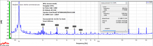
I did some initial tests to apply a positive voltage to the Anode when running the 4P1L in "screen mode" or using the screen as anode with FFT. It seems like applying 12-12.5V to the anode can reduce the H2 significantly. The actual response is really good. At 10Vrms output you only get 0.01% with H2 at -63dB and H3 and -65dB against 0.03% (H2 @ -53dB and H3 @ -51dB).
Need to apply the changes to the Mule preamp board and listen to it.
It’s quite sensitive to the voltage I found and I suspect there will be a variance between valves so the average impact may be not that optimistic
Ale
Need to apply the changes to the Mule preamp board and listen to it.
It’s quite sensitive to the voltage I found and I suspect there will be a variance between valves so the average impact may be not that optimistic
Ale
Sonic influence of H2 distortion
You may also find that phase of H2 also change with the adjustment. In case it may be of interest, Nelson Pass remarked about the sonic effect of phase of H2 on his F6 article: " The two phases of second harmonic do sound different, in fact the most consistent observation people have reported is that positive-phase has a little more projection to it, that it's a little more in-your-face and immediate. Negative phase tends to add more depth.", which generate some discussion on Adjusting P3 - a Video thread. A preferred setting can be found using soundcard, FFT and listening, but a notch filter or a distortion analyzer with distortion output is needed for visual observation of the waveform on the scope.I did some initial tests . . . to the anode can reduce the H2 significantly. . . . Need to apply the changes to the Mule preamp board and listen to it. . . .
Hi Indra,
Quite interesting, but haven't measured any change in phase. In fact, I can't see how the phase of H2 will change with the given circuit. The harmonics are below 80dB and frankly, I'd probably personally struggle to notice such a minor difference.
See attached.
thanks
Ale
Quite interesting, but haven't measured any change in phase. In fact, I can't see how the phase of H2 will change with the given circuit. The harmonics are below 80dB and frankly, I'd probably personally struggle to notice such a minor difference.
See attached.
thanks
Ale
Attachments
- Home
- Amplifiers
- Tubes / Valves
- 4P1L DHT Line Stage