PS, You could always go back to previous design and try bootstrap load of Q25 / 26 with capacitors. Sort of like Greg Balls SKA amp.
This should add OLG but retain DC conditions for VAS.
Z
Why do you think bootstrapping will increase OLG?
Why do you think bootstrapping will increase OLG?
I am referring to the non active load IP stage. Q25 can bootstrap R5 and Q26 can bootstrap R6. This will create a 'pseudo active' load.
The bootstrap is made by splitting R5 (1k5) into 2 x 750R resistors in series
and drive the junction between them with a cap from the emmitter of Q25.
Same for the lower side.
T
No problem with VAS DC condition with this CMs.
I tried a CMLC with not so good result as it was not so easy to compensate.
In simulator with ideal matching of devices, maybe but in real life I doubt it
will be DC stable.
Have you built this amp and tested it?
T
I am referring to the non active load IP stage. Q25 can bootstrap R5 and Q26 can bootstrap R6. This will create a 'pseudo active' load.
The bootstrap is made by splitting R5 (1k5) into 2 x 750R resistors in series
and drive the junction between them with a cap from the emmitter of Q25.
Same for the lower side.
T
I tried it and it really decreases distortion below 10kHz but doubles 20kHz distortion, and I don't like big electrolytic caps in that place.
THD below 10kHz is low enough without that bootstrap.
By the way inner FB loop around IPS and VAS is stable, LTspice behaves sometime strange after a few schematic corrections, and I could not get the same plot again.
In simulator with ideal matching of devices, maybe but in real life I doubt it
will be DC stable.
Have you built this amp and tested it?
T
No I haven't and probably will not as the complication is not so much better then simpler circuit. It was just an exercise.
Hi Guys
With just 2p5 as part of the nested loop value, it seems like this would be competing with stray capacitances of the layout? Is this a concern or is the value not too critical?
Have fun
With just 2p5 as part of the nested loop value, it seems like this would be competing with stray capacitances of the layout? Is this a concern or is the value not too critical?
Have fun
Hi Guys
With just 2p5 as part of the nested loop value, it seems like this would be competing with stray capacitances of the layout? Is this a concern or is the value not too critical?
Have fun
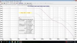
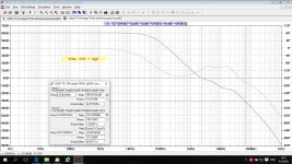
Not to critical. With 5pF THD at 20kHz will increase by 3dB.
Attached LG with 2.5pF and 5pF, 100% increase.
Attachments
Even though I was late, but congratulations. The model is very good.
Thank you T117.
As you could see in my previous post I am not using IRFP(9)240 since I do not have sufficiently matched pairs. I use FQA12N(P)20 mosfes instead. I have these matched very well. I intended to use them in PASS F5, bud finaly I decided not to make it. I am finishing my period of A class amps 😀
Attachments
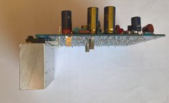
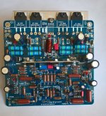
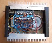
Here is picture of progress with these boards. I used older boxes from Pass A class monoblocks. At this moment the first one is working properly. It has 42 mV offset at the output and the current through output devices is approximately 70 mA pre device - 140 mA in total.
One monoblock was already tested with speaker, everything was working properly. When I will finish the other one I will post some listening tests.
P.S. Next week I am in Croatia for holiday, so I am sending greetings to Damir. 🙂
One monoblock was already tested with speaker, everything was working properly. When I will finish the other one I will post some listening tests.
P.S. Next week I am in Croatia for holiday, so I am sending greetings to Damir. 🙂
Attachments
Here is picture of progress with these boards. I used older boxes from Pass A class monoblocks. At this moment the first one is working properly. It has 42 mV offset at the output and the current through output devices is approximately 70 mA pre device - 140 mA in total.
One monoblock was already tested with speaker, everything was working properly. When I will finish the other one I will post some listening tests.
P.S. Next week I am in Croatia for holiday, so I am sending greetings to Damir. 🙂
I am glad that it's working even with different mosfet. I hope you have 42 mV of DC offset with no DC servo inserted.
If you pass via Zagreb you can visit me, I will PM you my mobile number if you do.
Damir
PS. You used wrong thread for this one, it should be in 200W CFA, this one is
for bipolar output.
Hi Damir,
Thank you for remind, I will post my listening tests in the right thread.😕
The offset is higher due to bigger difference between N and P devices. According to Nelson it is better matched in parasitic capacitances, however it it worse in gate to source voltage. In my case the difference between Vgs is 1,8V i.e. 3,9V vs. 5,7V. Without LF411 the offset is 1,2V.
P.S: Thank you for your kind invitation, unfortunately the bus I am taking will not go through Zagreb
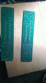
work in progress,, relayout from mr.alex 🙂
Nice boards, but I think you showed it in the wrong thread. It's maybe for 200W MOSFET CFA amp thread? 200W MOSFET CFA amp
No sir.
This is cfa unique bipolar output transistor. ��������
This is cfa unique bipolar output transistor. ��������
No sir.
This is cfa unique bipolar output transistor. ��������
My fault, at look on the PCB I made wrong assumption.
By the way I never built that amp, and I am very interested with the result.
- Home
- Amplifiers
- Solid State
- Unique CFA 120/230W amp