Actually a removable and replaceable stylus is a cheap and great idea, it just needs screw down rigidity
Hi Avwerk-
These 2 rough sketches may help you if you open one up. My knowledge is based on a sample of 2 so you are on your own-
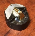
The brown goo, about like hardened contact cement is dribbled into these things and some may get in contact with the fine wires. When the plate is removed it will pull on the wires.
The example in the photos I posted...the top plate almost fell off the cartridge and either I snapped the wire when I lifted up the plate or it snapped when it moved around in its box. I got lucky though with the break about 3/8" out of the strain gauge, so plenty to solder to. The top had been held on mostly by the glob in the nose.
The 2nd example had one of the strain gauges go open so recently I opened it up.
I pried up the plate over the pins enough to shine a bright light in and could see it tugging at the wires, and pushed something sharp in and gently separated the wires from the plate.
Maybe a piece of tape wrapped around the nose to act like a hinge would be a good idea.
Neither of mine had any adhesive at the top of the plate near the screw mounts that was actually in contact with the wires but both units did have adhesive there so it could be a possibility.
Let us know what you find-
Dave
These 2 rough sketches may help you if you open one up. My knowledge is based on a sample of 2 so you are on your own-
The brown goo, about like hardened contact cement is dribbled into these things and some may get in contact with the fine wires. When the plate is removed it will pull on the wires.
The example in the photos I posted...the top plate almost fell off the cartridge and either I snapped the wire when I lifted up the plate or it snapped when it moved around in its box. I got lucky though with the break about 3/8" out of the strain gauge, so plenty to solder to. The top had been held on mostly by the glob in the nose.
The 2nd example had one of the strain gauges go open so recently I opened it up.
I pried up the plate over the pins enough to shine a bright light in and could see it tugging at the wires, and pushed something sharp in and gently separated the wires from the plate.
Maybe a piece of tape wrapped around the nose to act like a hinge would be a good idea.
Neither of mine had any adhesive at the top of the plate near the screw mounts that was actually in contact with the wires but both units did have adhesive there so it could be a possibility.
Let us know what you find-
Dave
Attachments
Kevin, you are right, tonight I put a glob of blue tack as you did and use a piano recording for test, the effect is immediate audible, with the damping the attack of the piano is more controlled and without sounds a little splashy if you know what I mean!
Yes, I know exactly what you mean! I think "the blob" is now mandatory on both of mine.. LOL
There was a noticeable clean up on the highs and noticeably better separation in the highs as well.
The 450C (not CII) has entirely different construction and the strain gauges in that design apparently couple to the top where a good head shell presumably might help even more than with these cartridges.
Thanks For the heads up on pulling one apart
Solvent might be the next step in separating
Regards
David
Solvent might be the next step in separating
Regards
David
Thanks For the heads up on pulling one apart
Solvent might be the next step in separating
Regards
David
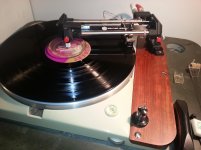
Please keep us updated. I will try to mod the cartridge too later on. Here is a photo I did for my Denon DL-103R. The body is African Black Wood and I made the body myself. The weight of body may be too heavy for most of arms, but it is no problem for my diy air bearing arms. From the description of strain gauge cartridge sonic characteristics, wood body may be a good choice.
Attachments
First time for me also
Find a scrap SMD board to practice on just before going for it
What helped me was to use a needle point soldering tip, smallest dia. Solder (.020")
Flux pen and cleaned surface with a magnified light
Support for both hands and proper angles
No coffee or music playing for concentration
I actually enjoyed it , but could see how you might create a mess if you don,t follow all the steps
Youtube was very helpful overall also.

Regards
David
Find a scrap SMD board to practice on just before going for it
What helped me was to use a needle point soldering tip, smallest dia. Solder (.020")
Flux pen and cleaned surface with a magnified light
Support for both hands and proper angles
No coffee or music playing for concentration
I actually enjoyed it , but could see how you might create a mess if you don,t follow all the steps
Youtube was very helpful overall also.
Regards
David
Last edited:
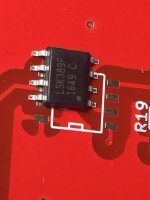
Also prewet 2 pads in opposite corners and find a weighted needle to place on the SMD and touch these first to anchor the jfet
The dot on the jfet and pcb rectangle give you orientation
The dot on the jfet and pcb rectangle give you orientation
Last edited:
Yes, that is correct!
I usually wet just one - usually the one that is most comfortable for me to place the part using tweezer in one hand and solder iron in the other.
I then solder all the rest.
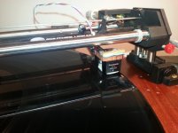
Dave, that is a very tidy build.
Have you listened to it at all yet?
I played both the rev. 2.0 and rev 2.1 pre-amps and their respective cartridge/arm/table combination for a friend today who will likely post his thoughts at some point here. (He has a rev. 2.1 kit, and a couple of different strain gauge cartridges)
I usually wet just one - usually the one that is most comfortable for me to place the part using tweezer in one hand and solder iron in the other.
I then solder all the rest.
Dave, that is a very tidy build.
Have you listened to it at all yet?
I played both the rev. 2.0 and rev 2.1 pre-amps and their respective cartridge/arm/table combination for a friend today who will likely post his thoughts at some point here. (He has a rev. 2.1 kit, and a couple of different strain gauge cartridges)
I have no more rev 2.1 boards or transformers available at this point.
I do have a single pair of rev. 2.0 boards and a PSU board if anyone is interested.
If there is sufficient interest in the not too immediate future I may entertain the possibility of another group buy.
I do have a single pair of rev. 2.0 boards and a PSU board if anyone is interested.
If there is sufficient interest in the not too immediate future I may entertain the possibility of another group buy.
I need the 1n5408s + 10ohm/2wt for the PSU grd. Failed to order them
Next week start up for sure
Regards
David
Next week start up for sure
Regards
David
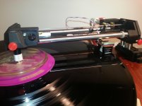
450C has landed
Initial impressions are favorable, although it clearly needs a new stylus.
I have ordered the $70 Bliss replacement from
EPS-45STQD Type Stylus for EPC-450C Panasonic Cartridge - our Needle 678-DQ
I've had very good results with Bliss styli on my other two strain gauges so I figured why mess with success, and until I am completely sure about this cartridge I did not want to overspend.
Surprisingly it is quite high compliance and mounted on one of my lighter shells and tracking at about 1.2gms which seems to faze it not at all.
I like it a lot so far and will work on optimizing the set up over time. There are some things about it I will talk about once I get the new stylus. What I can tell you is that it is a good match to my pre-amp design, either revision.
Attachments
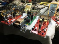
Been running a couple hours
Wall AC -119vac
J3 - 295.0 v
J7 - 24.37 v
J8 - 6.26 v
Temperatures
Ambient - 28 C
LT 1085 sink -46
U1 pad 36 C
U2 pad 42 C
D5 36 C
D6 58 C duh!
This one gets redone. Either to the alum. enclosure with a small fan in back blowing forward since temps are going up once stuffed inside..,.,
Knew this was coming as Kevin warned us !
More holes and maybe thru the PCB in choice locations
Attachments
I don't think 58C is too bad, and I strongly recommend you not drill through the pcb.. LOL I suspect drilling a few holes directly above the heat sink is sufficient as long as there are other holes in the case to let air in.
Voltages all measure well with the acceptable range.
Looking forward to reading your listening impressions.
One thing I noticed (I think) is that there is more than one ground connection to the PCB from the PSU, this will create a ground loop. I used a single ground connection at the +300V input. I believe you have one at the -24V supply and the +300V supply connections as well. I think either would be fine, but not both. (A learning moment for me)
I ordered my two chassis from diy store here. The chassis has quasi heatsinks on both sides. I can mount the parts on the side wall if necessary.
Another question. My preamplifier has a switch to invert phase so I need to invert the phase when I use the SG phono .
Another question. My preamplifier has a switch to invert phase so I need to invert the phase when I use the SG phono .
The only part you should consider mounting on the chassis is the filament rectifier. Mounting any of the active components on the chassis from either the power supply or audio boards is likely to result in oscillation and degraded performance.
Yes you need to invert one channel relative to the other. For me that is generally the right channel. (My pre-amp has separate polarity/mute switches for each channel)
Yes you need to invert one channel relative to the other. For me that is generally the right channel. (My pre-amp has separate polarity/mute switches for each channel)
My preamplifier is Audio Research Reference II. I believe it inverts phase for both channels. Can I wire the output of right channel on the SG phono out of phase? So, I don't need to do anything else.
Last edited:
Unfortunately that will not work, you will have to invert the phase at the speaker or use a pair of 1:1 transformers, one of which would be connected to invert the output phase.
- Home
- Source & Line
- Analogue Source
- Playing With Panasonic Strain Gauge Cartridges (And A Dedicated Phono Stage)