Got the new mains transformer in today, (30-0-30v) also replaced R9 12k with 8.2k 1 watt metal film, (Runs much cooler) and R2 from 47k to 33k.
Initial tests look promising, the supply rails are now +/- 43v with just one amp connected and in the bias setting state i.e. no output load, The DC offset has also dropped down a bit to 14mv on one channel and 20mv on the other, not had chance to scope the output yet, hopefully tomorrow I can bring it indoors from the workshop (Big Garden Shed) 😱 and away from the solar panels and inverters which I know generate a huge amount of RF noise (when the sun shines)...... So should get a better idea of how clean the output is.
Initial tests look promising, the supply rails are now +/- 43v with just one amp connected and in the bias setting state i.e. no output load, The DC offset has also dropped down a bit to 14mv on one channel and 20mv on the other, not had chance to scope the output yet, hopefully tomorrow I can bring it indoors from the workshop (Big Garden Shed) 😱 and away from the solar panels and inverters which I know generate a huge amount of RF noise (when the sun shines)...... So should get a better idea of how clean the output is.
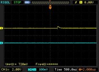
Had Chance to take some scope measurements of the amps today, not sure how the images will show up, so please bear with me, might have to edit and explain as I go.
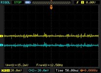
The first image is with the amp turned off, and the noise present is just pickup from the speaker leads.
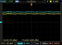
The second is showing the noise and DC Offset after 30mins, There looks as there is a slight amount of ripple, but the readings were taken with the inputs Open, and putting a hand nearer to the board would make this worse, I'm hoping that once the top is fitted this might disappear.
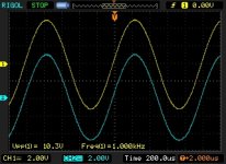
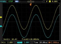
These two, show a 1Khz and 10Khz Sine wave.
The Next few show a square wave with respect to the input signal (Lower Trace)
The amp didn't like 10Hz too much, I was also looking to see if the signals were in phase, or out ..... Depending on how you look at it ...
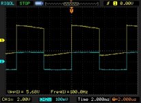
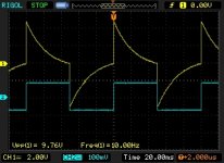
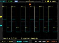
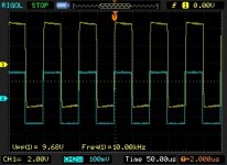
Finally, the Switch on pulse at the output.
The first image is with the amp turned off, and the noise present is just pickup from the speaker leads.

The second is showing the noise and DC Offset after 30mins, There looks as there is a slight amount of ripple, but the readings were taken with the inputs Open, and putting a hand nearer to the board would make this worse, I'm hoping that once the top is fitted this might disappear.

These two, show a 1Khz and 10Khz Sine wave.


The Next few show a square wave with respect to the input signal (Lower Trace)
The amp didn't like 10Hz too much, I was also looking to see if the signals were in phase, or out ..... Depending on how you look at it ...


Finally, the Switch on pulse at the output.

So far so good. The 3mV or so of ripple in your second image is higher than I'd like to see. But it has been a long time since I built this sort of circuit. This may be poor PSRR or some noise getting in.
Did you implement the 2 bridge rectifier arrangement?
Did you implement the 2 bridge rectifier arrangement?
Last edited:
No, I'm still using a single Bridge Rectifier.
The strange thing about that ripple is I can make it worse by putting my hand nearer to the boards.
I'm hoping that once the top is finally screwed down it may help screen it and improve it, the measurements were carried out with the top off as I needed to access the input connections on the boards, I now have the RCA connectors connected up, but haven't had time re check to see if there has been an improvement.
Is the input shorted to ground? LTSpice shows that the input should be a mirror image of the feedback for best hum rejection. Same capacitor value, 33k and 1k
Please post a photo of the inside.The strange thing about that ripple is I can make it worse by putting my hand nearer to the boards.
What happens to the ripple if you touch a transistor can?
Is the input shorted to ground? LTSpice shows that the input should be a mirror image of the feedback for best hum rejection. Same capacitor value, 33k and 1k
No, The inputs were left floating, and probably the reason putting my hand near to the boards increased the pickup, I should really have grounded the inputs in hindsight.
As for the input, it's almost a mirror, 33k and 2.2k 🙂
Please post a photo of the inside.
What happens to the ripple if you touch a transistor can?
Don't have an up to date photo at the minute, I'll grab one as soon as I can.
Touching the transistor cases has no effect, doesn't cause any oscillation or make the pickup worse, it's only if I hover my hand over the area near the input pins that causes the pickup to increase, like I mentioned in the post above, I should have grounded the inputs before making the measurements.
Why Not?Don't use this design with passive preamps
Surely a passive preamp is just a potentiometer equivalent but in a separate box - all the normal rules for using a passive would apply - short leads probably being the main one.
The Maplin circuit has good supply rejection when driven from a low impedance source, thanks to some clever design by Hitachi. Drive it from 10s of k and this does not happen
Don't use this design with passive preamps
Hi, I was planning to run the amps with the Rod Elliot Hi-Fi Pre amp (P97)
Hi-Fi Preamplifier
I would increase the Rod Elliot output capacitors to 10uF or more.
Better still eliminate completely as the Maplin is AC coupled in anyway. Not much point capacitor in series with a capacitor
Better still eliminate completely as the Maplin is AC coupled in anyway. Not much point capacitor in series with a capacitor
The Maplin circuit has good supply rejection when driven from a low impedance source, thanks to some clever design by Hitachi. Drive it from 10s of k and this does not happen
So I'm interested enough to want to know more.
I have lots of lateral mosfet amps using variants of this circuit.
Some have balanced inputs with an op amp buffer. Most have a volume pot before the input differential pair. Most apart from the Maplin amps have a CCS for the input diiferental pair supplying about 1mA.
I would say that I dont like to use a source impedance over 10K.
Regards Xoc1
Ok, Rod Elliot stuff aside for the moment, I have a bigger problem to sort out with that project at the moment, Not PCB wise, but Case problems, the Front panel of the case is 8mm thick Aluminium, so none of the control shaft threaded sections are long enough to pass through, I have a CNC Machine shop near me who is going to Route out a large 5mm deep section leaving a 3mm thick part for the pot and selector switch threads to fit through, I love the challenges DIY Stuff throws up 😀
Back to the Maplin Amps, and some earlier posts regarding proper grounding of the inputs.
I have modified the boards as Traderbam Suggests in post #48, all Grounds go back to the Star Ground at the PSU Caps 0v, Including the Chassis Ground, and Mains Ground.
In Post #261 by "ivanlukic" and the Bonsai attachment, It shows the input ground De Coupled by a 1nf cap to chassis ground, Something I have yet to implement, and before I do, would appreciate any comments regarding that because I'm pretty sure someone will come along and say "Yes" but it needs to 10nf or 47nf😀 😕 🙁
Quite a good test for general issues with wiring is to connect a dummy load to one channel, and a speaker to the other. Now apply a shorting plug to the input of the channel connected to the speaker and drive the channel connected to the dummy load hard (1kHz sine at a few watts).
You should not hear anything from the speaker.
Repeat by swapping all the connections around for the other channel.
You should not hear anything from the speaker.
Repeat by swapping all the connections around for the other channel.
Quite a good test for general issues with wiring is to connect a dummy load to one channel, and a speaker to the other. Now apply a shorting plug to the input of the channel connected to the speaker and drive the channel connected to the dummy load hard (1kHz sine at a few watts).
You should not hear anything from the speaker.
Repeat by swapping all the connections around for the other channel.
That Makes sense, I can probably try that without too much problem.
With regard's to the 1nf connected to the RCA Input Ground and Chassis, Is 1nf a pretty common value for that purpose?
The RF attenuation filter on the input uses a reactance in series with the Signal+Interference and another reactance shunting the Signal+Interference to chassis, or to Signal Return/Cold.
You need both parts to create a filter.
Usually we see RC filters on the input, but there is a hidden element in there that is not specified. The cable (and possibly the source) has some inductive reactance.
If there is no "R", then only the cable+source inductance interacts with the input capacitor to create an LC filter that is 2pole (-12dB/octave = -40dB/decade).
But we usually ignore that one because we are not given inductance data.
Using the conventional RC filter (single pole with -20dB/decade), we usually filter somewhere between F-3dB = 30kHz and F-3dB = 1MHz.
Going as high as 1MHz lets a lot of the RF in and that can cause distortions and misbehaviour inside the Receiver.
Going as low as 30kHz will remove some of the audio/treble content.
You need to select a compromise value that suits your equipment and your ears and your levels of interference.
1000r +1nF gives an F-3dB = 1/{2 Pi R C} = 1/{2*3.14*1000*0.000000001} = 160kHz. (see why we use "n" with nF, it avoids all those zeros)
Last edited:
I've never used them. I imagine 1nF is plenty big for this purpose. I think you just have to see for yourself whether they make any difference.In Post #261 by "ivanlukic" and the Bonsai attachment, It shows the input ground De Coupled by a 1nf cap to chassis ground, Something I have yet to implement, and before I do, would appreciate any comments regarding that because I'm pretty sure someone will come along and say "Yes" but it needs to 10nf or 47nf😀 😕 🙁
The RF attenuation filter on the input uses a reactance in series with the Signal+Interference and another reactance shunting the Signal+Interference to chassis, or to Signal Return/Cold.
You need both parts to create a filter.
Usually we see RC filters on the input, but there is a hidden element in there that is not specified. The cable (and possibly the source) has some inductive reactance.
If there is no "R", then only the cable+source inductance interacts with the input capacitor to create an LC filter that is 2pole (-12dB/octave = -40dB/decade).
But we usually ignore that one because we are not given inductance data.
Using the conventional RC filter (single pole with -20dB/decade), we usually filter somewhere between F-3dB = 30kHz and F-3dB = 1MHz.
Going as high as 1MHz lets a lot of the RF in and that can cause distortions and misbehaviour inside the Receiver.
Going as low as 30kHz will remove some of the audio/treble content.
You need to select a compromise value that suits your equipment and your ears and your levels of interference.
1000r +1nF gives an F-3dB = 1/{2 Pi R C} = 1/{2*3.14*1000*0.000000001} = 160kHz. (see why we use "n" with nF, it avoids all those zeros)
OoooKay ...... That's quite a bit to take in, Think I'll just try with and without 1nf and see if there is a difference 🙂 But thank you for going into such detail.
- Home
- Amplifiers
- Solid State
- Any Maplin MosFet Amp Guru's on here?