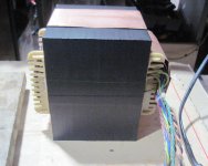
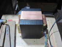
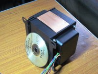
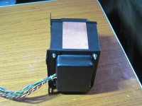
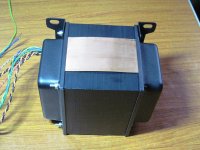
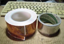
0.3 mm copper banding installation....
traffo is for a 4d32 pp amp i am building....1 3/4 inch center leg stacked to 4 inches...
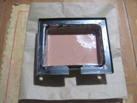
end-bells tend to buzz so i added a 6 mm thick epoxy lining on the inside of end-bells....
traffo is for a 4d32 pp amp i am building....1 3/4 inch center leg stacked to 4 inches...
end-bells tend to buzz so i added a 6 mm thick epoxy lining on the inside of end-bells....
Attachments


What does the copper band do for the EI transformer performance/parameters?
Are the effects audible, or measureable?
Does it improveme interference EMI?
Are the effects audible, or measureable?
Does it improveme interference EMI?
helps in stray field and noise reduction,
unfortunately i can not measure...
on many Japanese traffos that i rewinded,
they even put a metal band one or two laps
around the outside of the traffo core.....
i will do that one day....
i got all these ideas from tearing down many gears
coming out of America and Japan.....
unfortunately i can not measure...
on many Japanese traffos that i rewinded,
they even put a metal band one or two laps
around the outside of the traffo core.....
i will do that one day....
i got all these ideas from tearing down many gears
coming out of America and Japan.....
Attachments
Yes, I have seen many photos showing the EI belly band.
But I have never seen any comparative data on what the belly band brings to performance, either in transformer parameters, or in amplifier performance.
But I have never seen any comparative data on what the belly band brings to performance, either in transformer parameters, or in amplifier performance.
first time for me see one was in our 21 inch Admiral black and white TV set in 1961...
they must have known something back then that we did not....
they must have known something back then that we did not....
Our first television bought in 1959 and still in use for at least 5years was a lot smaller, maybe 15".
It probably did not have a mains transformer and probably used a big multi-tapped resistor to feeds mains voltages to the various parts of the valve/tube circuits.
It probably did not have a mains transformer and probably used a big multi-tapped resistor to feeds mains voltages to the various parts of the valve/tube circuits.
Might be why the UK adopted the fused plugtop with polarized pins so that we could rely on the plug/socket to protect us from ourselves !
i have not seen documents as to why american traffos used the copper band in their
traffos, i am sure such documents exist....ping Bud Purvine...
traffos, i am sure such documents exist....ping Bud Purvine...
Transformers for Electronic Circuits - Grossner
Section 9.4: Design of the Coil
a. Leakage Inductance ...
b. Push Pull Coupling ...
c. Capacitance ...
1.
2.
3. Common Mode Coupling.
In low level circuits signals must be distinguishable from spurious currents which flow in the ground or common circuit. It is possible to reduce such currents by using an electrostatic shield between primary and secondary windings.
A substantial reduction of spurious currents, that is, common mode coupling, is obtained by the use of two screens between the windings. One screen, connected to the high side of the primary, serves to short circuit a ground current which might otherwise flow via stray capacitance through the primary. The other screen, connected to the grounded secondary terminal, serves to bypass current which might flow through the bridging capacitance between windings.
The measure of efficacy used is called common-mode rejection.
There is also a reference to an article if anyone fancies digging it up from the grave:
B Sommer, G Plice, "Specification and Testing of Shielded Transformers", Electro-Technology, Vol 71, No 5 [May 1963]: 102-105
.... are grounded secondaries used in SE transformers ?
it is outside the magnetic circuit so it is in fact a shorted turn and does not interfere with normal traffo action.....
donny, i have seen that, and many others, perhaps what andrewt wants to see
are some basic computations as to how to do it...
for me, as long as it works, and i can diy it, then i will do it...
are some basic computations as to how to do it...
for me, as long as it works, and i can diy it, then i will do it...
"it works" ?
What does it achieve?
How do you know it works?
What if the belly band was 1mm thick and 1mm wider than the iron core window height?
Alternatively, what if it were 0.1mm thick and only 10mm wide?
Do both work as effectively, or does only one work? How do you know?
What does it achieve?
How do you know it works?
What if the belly band was 1mm thick and 1mm wider than the iron core window height?
Alternatively, what if it were 0.1mm thick and only 10mm wide?
Do both work as effectively, or does only one work? How do you know?
just DIY it and find out for yurself...
what i mean by "it works" is that the traffo operates
as it should, no smoke comes out....
sensible DIY means that building the traffo so that
there is no chance for any windings and pigtails
touching screens and belly bands, this is a no brainer...
hey this is my DIY, i am happy doing it and that is all that matters to me...
not for me to question what Amercan traffo makers found as good practice, i find it makes sense to me and i follow it..
from: http://www.diyaudio.com/forums/power-supplies/220511-transformer-shielding.html#post3184468 30th September 2012, 06:19 PM
Andrew,
internal copper shields are electrostatic screens, and have the following constraints:
- must not create a shorted turn
- needs to have its ends insulated.
- must be connected to an appropriate AC return. A primary screen should be connected to either +Vdc_in or -Vdc_in (the input supply return). And a secondary screen should be connected to either Vout or 0V (its return)
[note my careful avoidance of the term "ground" - I use "protective Earth" when I mean exactly that]
- should have its connection in the center (lowest impedance from either end)
- must be very thin (to minimise eddy current losses)
- must have high resistivity (to minimise eddy current losses)
- needs a low inductance connection - the interconnect inductance controls the HF behaviour of the shield. this is true of all shields, be they internal electrostatic shields or external belly bands. long skinny wires pretty much ruin shields.
one cute trick for a foil winding is to add one extra turn after the DC end (usually 0V) as a shield with a free interconnect. its very easy to do, but may increase shield losses because the foil is invariably a lot thicker than a separate shield could be, and the shield connection is highly asymmetric. on the plus side its really, really easy to do.
A Gauss Band, or belly band, or flux shield has an entirely different set of constraints. Unlike an internal E-screen which is fully immersed in the transformer flux, a belly band is loosely coupled - its only the leakage flux that cuts it, and that ought to be fairly small.
so no matter how thick you make your belly band, you have almost no influence on the transformer operation at all (which is what we expect) - or to look at it another way, the eddy currents that leakage flux causes in a belly band are pretty much constant. its loosely coupled, so behaves like an independant current source.
So to minimise losses in belly band, you need to:
- form a closed loop
- use thick shield material
- use conductive sheet material (these two minimise I^2R by minimising R)
all three of which are the exact opposite of an internal electrostatic screen.
it also needs:
- to be insulated (thats an electrical safety thing, it wraps around the xfmr so gets close to pri and sec and core)
- to have a low inductance connection to a suitable AC return (I have used both -Vdc and 0V in different designs, for reasons of convenience)
a belly band can also be used to connect the core itself to some convenient AC return.
toroid
sir tony may i ask if i can get 1500VA on the following toroid?
OD = 8"
ID = 3"
H = 6cm
i do not have a concrete formula on toroid...
thank you
sam
sir tony may i ask if i can get 1500VA on the following toroid?
OD = 8"
ID = 3"
H = 6cm
i do not have a concrete formula on toroid...
thank you
sam
- Home
- Amplifiers
- Power Supplies
- Tony's latest traffo DIY build