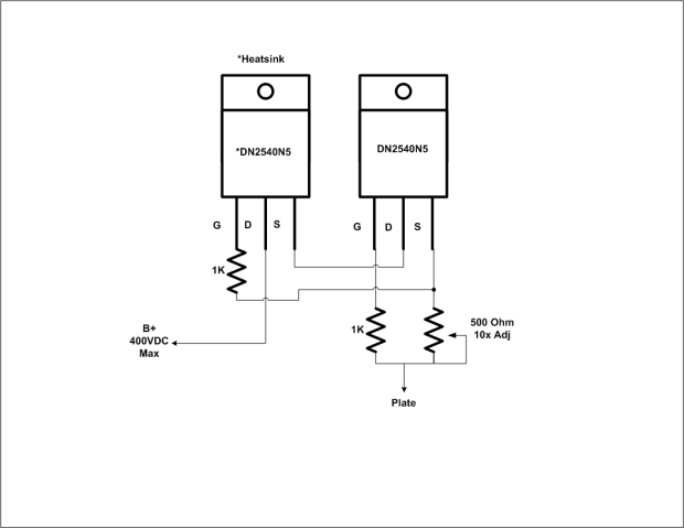
I would build the circuit with two transistor current sources, instead of the classic LED+ transistor, these have a higher AC impedance. Secondly, i'd refrain from using pots as resistors to set the current. Use a fixed resistor with a pot in parallel. In that way, if the contact of the pot goes bad, the circuit keeps operating.
Secondly your IRF840 could do with a NPN transistor that prevents overcurrent, the circuit as shown will blow up if you overload it, I have good experience using TO247 IGBT's as linear pass elements, their Safe operating area is such that they will survive even the worst overloads if you take some precautions. These include a resistor in series with the emitter, which turns on a NPN transistor (General purpose BC547 will do) if there is a short down the line. Adding some resistance in the order of 10-22 ohms in series with the collector also helps to limit the peak current before the transistor can discharge the gate capacitance.
Led biasing has one nasty disadvantage, the steep slope of the Led means that there is no "Automatic" compensation for the ageing of the tube. Normally the Ri and anode resistance/cathode feedback keep the tube operating pretty consistently over its lifetime. You could add some resistance in series with the Led. Also don't forget to bypass them, 10-47uF will do.
Yes, those where some of the things i noticed about the schematic.
IRF840 based power supplies work good, but are prone to failure if the mosfet needs to do a lot of current into a low R load (Like charging a capacitor) Most Mosfets/IGBT's cannot charge a large value capacitor because this would exceed their safe operating area. However if you build the circuit with a NPN current limiter (Essentialy making a N-Fet /NPN current source) this becomes less of an issue. However most mosfets/IGBT's will still exceed their SOA at startup.
I built a high stability 250V 150mA supply using a LTP transistor to control an IGBT . It works quite well and survives a dead short with a screwdriver. If you add three parts to your power supply, and perhaps change to a beefy IGBT my guess is that yours will aswell. Then you can add an electrolytic on the output.
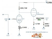
Using a led and a ccs on the simple schematic has the nasty side effect of getting as much gain as you can from the input tube.. which is usually way too much in practice for headphones amps.
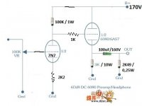
The 3K/5W resistor will burn itself up, use a 10W part.
The 6922 has too much gain for the circuit, use a 6CG7 or 5687 instead.
100uF is a decent choice for the coupling cap.
The 6922 has too much gain for the circuit, use a 6CG7 or 5687 instead.
100uF is a decent choice for the coupling cap.
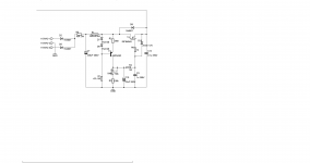
You can check the datasheet for the 6SN7 for reccomended anode grid leak and cathode resistances. @ 150V B+ The anode will then hopefully bias up at +80V with respect to ground. Then you can choose whether to have the tube directly coupled to the 6080 or to include a RC bias circuit.
Edit i just checked for you, 2K2 cathode resistor, 100K anode resistor, 100K grid leak (Or the direct coupled pot like you show in your drawing. Gain will be about 24-28. You can and should bypass the cathode resistor
Edit i just checked for you, 2K2 cathode resistor, 100K anode resistor, 100K grid leak (Or the direct coupled pot like you show in your drawing. Gain will be about 24-28. You can and should bypass the cathode resistor
Last edited:
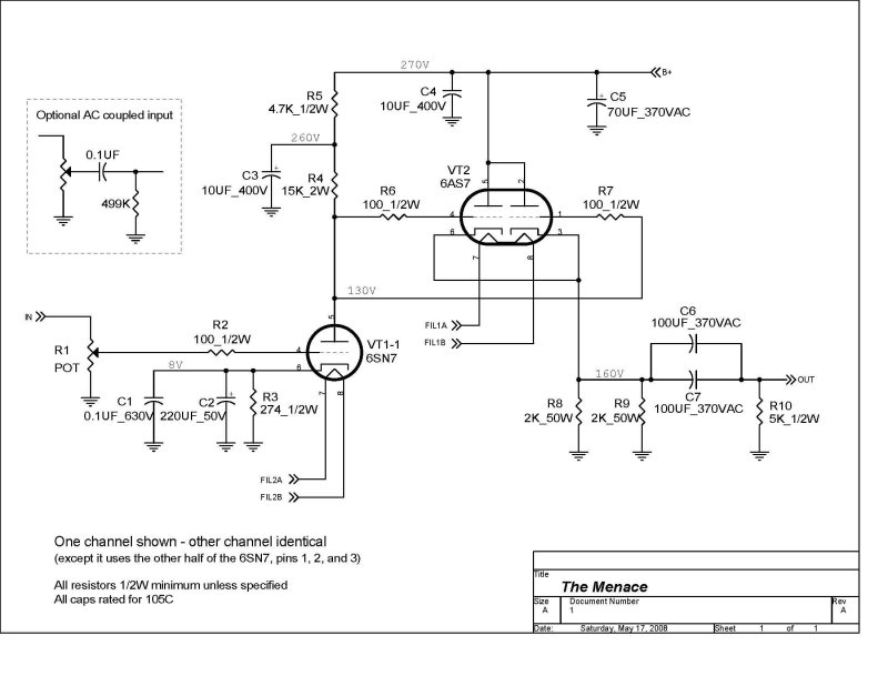
Yes that is another implementation, Note that Pete runs his 6SN7 quite hard at ~8mA of current, generally the 6SN7 is more linear in the higher current ranges.
Edit i just checked for you, 2K2 cathode resistor, 100K anode resistor, 100K grid leak (Or the direct coupled pot like you show in your drawing. Gain will be about 24-28. You can and should bypass the cathode resistor
I'm sorry I didn't read your edit, thank you.
How to implement CCS for 7N7 in place of 100K anode resistor?
Could I use this schematic?
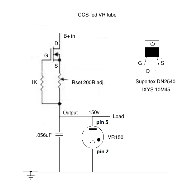
Or this one for cascode without cap & VR tube?
Could I use this schematic?
Or this one for cascode without cap & VR tube?
Take the curves for the 6SN7, print them out. Draw a horizontal line at the current you're going to set your CCS to. then see which negative grid voltage intersects this line closely at half your anode voltage. Divide this voltage by the current and you have a cathode resistor.

That should work, note the 6080 grid wont consume a lot of current a few uA at most. However you could add a 1K resistor in series with
Its best to have a regulated power supply for measuring and evaluating these circuits, I have a 0-300V 0-100mA lab power supply for just this purpose. These are expensive if you need to buy a used unit, i was lucky enough to get two for €100 each.
Note that valve curves are curves that are the average of 10's of tubes.
- Home
- Amplifiers
- Tubes / Valves
- 6AS7 OTL headphone amplifier