if you want lower gain, just use small mu tube
There are very few tubes that actually fit those parameters. Sure, there are triodes with lower gain, but most of them need a heap of plate current and pretty high bias voltage. When you consider the operating current required, then you might end up losing your ability to directly couple, and the design falls apart a bit.
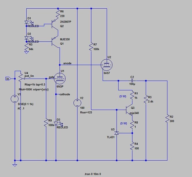
i do not understand the reason behind r3,r31
if ou want lower gain, just use small mu tube
Or leave the bypass capacitor off of the cathode of the 6SN7...
R3 should be bypassed with a film cap (100n~1uF) to prevent loss of signal, this will still set the DC to the 6AS7 grid the same as it currently stands.
In an application like this where you don't have large feedback loops to worry about there's no reason not to use them as needed.
..now i see.
it´s sad that coupling cap phobia is strong again. 🙁
If you're going to run a lot plate current on the output tube, making a self biasing cathode follower will end up being a bit of a pain in the butt. (More wirewound resistors)
You could bias it up more like a transistor, with a voltage divider from B+ to ground, but then you're injecting power supply noise into the grid.
Sometimes direct coupling is a sensible approach not motivated by phobias or religious preferences.
I wonder how a 12HL7 would work as an output valve?
gm= 21ma/V
The output impedance would be lower than 6AS7 and they are cheap.
gm= 21ma/V
The output impedance would be lower than 6AS7 and they are cheap.
Or leave the bypass capacitor off of the cathode of the 6SN7...
R3 should be bypassed with a film cap (100n~1uF) to prevent loss of signal, this will still set the DC to the 6AS7 grid the same as it currently stands.
But lose gain?
Thanks guys, question still without answer: It's possible to mod for cathode LED bias or cathode battery bias to improve the SQ?
New question: It's possible to improve the SQ changing the cathode resistor of 6AS7 for something like this schematic?
New question: It's possible to improve the SQ changing the cathode resistor of 6AS7 for something like this schematic?
But lose gain?
The r3/r31 divider is already reducing gain anyway, leaving the cathode resistor unbypassed doesn't hurt here because you are increasing the signal at the grid of the 6AS7 with the cap added across r3. A wash.
I'm sorry if I ask again: Are you saying bypassing R3 with 0.1-1uF cap and taking off the cathode capacitor of 6SN7 have the same gain?
The resistor divider formed by r3/r31 only passes 60 percent of the signal at the 6SN7's plate to the grid of the 6AS7. Installing a capacitor across r3 will pass the signal through without attenuating the AC component in the divider, while maintaining the existing DC voltage.
Quick and dirty math, so it isn't terribly exact, but close enough for this application (the tubes will vary more than the errors of my quick maths most likely)
Bypassed cathode resistor you will get a gain of maybe ~16 at these operating points (resistively loaded in the earlier schematic) so looks like: 16 x 0.6= 9.6. Unbypassed cathode resistor, but with r3 shunt capacitor will give you maybe a gain of 10, and slightly better linearity due to the internal feedback afforded us via cathode degeneration. Negligible difference, and in real world it might make a couple degrees difference in volume knob rotation, if it's even audible.
(if PRR wants to step in and do the math better I'm all ears)
Like I said, a wash. Given the choice, I'll take a smaller film cap when I can, as they tend to be a bit less likely to cost much for the size, and are generally less "obtrusive" to the sound and measurements. Likely to sound better too.
I like the wash, used teflon FT-3 capacitor 0.47uF to bypass R3, I'm happy with the mod thank you.
Glad you like it, and yes, just like that schematic. Larger cap will let the bass go lower, but .47uF is as high as I would go for headphones, so good choice, It's what I would have used.
Pete Millett also made a 6AS7 otl called the Wheatfield HA-2.
http://www.pmillett.com/Wheatfield/manual.pdf
The Apex Teton he currently makes is a scaled up version with everything refined to the max.
http://www.pmillett.com/Wheatfield/manual.pdf
The Apex Teton he currently makes is a scaled up version with everything refined to the max.
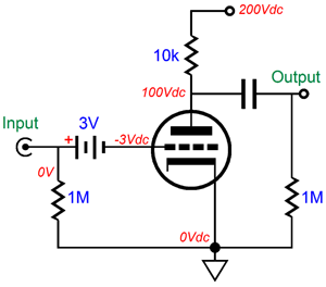
If you put the battery in series with the grid it wouldn't need the input cap. The battery won't discharge through the resistor when it's off, either. Picture from tubecad.com
Use a carbon cell, it has a long service life in this usage and doesn't mind heat as much as an alkaline.
Use a carbon cell, it has a long service life in this usage and doesn't mind heat as much as an alkaline.
Last edited:
I didn't used the input cap because all my source devices have output cap. I saw someone putting in parallel to the battery 1Meg + 10nF in parallel to the battery, why?
- Home
- Amplifiers
- Tubes / Valves
- 6AS7 OTL headphone amplifier