What difficulties should I anticipate with LT3042? Will I be able to work with heatgun and soldering paste?
I like to keep the buffer and powersuplly on same board.
I like to keep the buffer and powersuplly on same board.
Yeap, that's just exactly what it is...NONSENSE.thanks, just needed someone like You to tell me talking nonsense 🙄
Who in the hell is stupid enough to step on cutoff component leads in their own carpeting?? Funny...

The OP can do whatever he wants for a PCB for the Calvin buffer with a servo, but I avoid SMDs unless I have to absolutely use them.
If using matching input JFETs, the servo can be eliminated...sooo simple.
The Calvin buffer sounds okay, but keep in mind there are numerous better sounding options out there.
Now...let's bust out the moonshine and soldering iron and build something!😀
The OP can do whatever he wants for a PCB for the Calvin buffer with a servo, but I avoid SMDs unless I have to absolutely use them.
That's completely valid. Some of us go for ease of building, some for the best possible performance. This IS diyaudio after all.
Jan
The Calvin buffer sounds okay, but keep in mind there are numerous better sounding options out there.
D
Can you list those options please.
Hi,
Maybe it is, maybe it isn't the best sounding buffer for You.
The project started out as 'a simple idea' in first place, gained momentum when Joachim Gerhard found it to be an excellent little thing and Klaus Hesener implemented it into the Paradise phono.
At around #300 Ammel joined the thread and was helped by many participants, me beeing just one of them.
Especially towards the end of his build his version needed some tweaking (he already liked the sound even when it didn't work correctly then).
Now repeatedly claiming that I'd be talking nonsense and talking bad of the buffer seems like his 'thank You' for getting helped.
I'm drawing my own conclusions from that. 🙄
jauu
Calvin
Can you list those options please.
Some friendly advice.
If you want to ever finish your project, don't go there...
Jan
Some friendly advice.
If you want to ever finish your project, don't go there...
Jan
I was validating the claim made by Ammel.At least in simulation I like the Calvin'S design over some others. And Ammel seems like talking with some grudge in mind. He does not understand why the Servo is used.
Anyway going back to power supply, I posted in power supply design one that I have in mind for powering the buffer. What is more important in Calvins buffer PSRR or noise , or other words should I pick a PS with PSRR of above 120 with higher noise or PSRR of 70s and noise 4nV/Hz2.
Clavin ,mentioned it to me ,but I would like something on board than connecting multiple boards.Plus the PSRR of 60 is not that difficult to achieve.
Last edited:
Clavin ,mentioned it to me ,but I would like something on board than connecting multiple boards.Plus the PSRR of 60 is not that difficult to achieve.
Yes, there are many ways to skin your cat.
Hi,
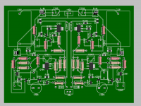
when You use SMDs for the transistors why not used SMD resistors ... size 0805 or 1206 is so easier to solder.
Two points that immidiately fell into my eyes were
- the power supplly lines were obviously routed at last. This typically leads tol inferior designs regarding the supply quality. A plus is that the schematics and the layout often look similar. It can be better though to place supply lines first as copolanars and then connect all the parts with a direct connection close to them and all other parts following outwards. Such a layout may not look at all like the schematic and may be more difficult to service, but signal integrity could be improved. (rem. coplanar here means that two wide traces V+ and V- are placed in parallel and the gnd trace, just on the other layer, thereby forming two capacitors ... FR4 is quite a good dielectric).
- U101 and 201 seem like SOT23-5 casings. Rather use SOT23 (SOT23-3) instead ... makes solderiung easier-
- The heat distributed from the collector pins of Q106 and Q206 requires some floor space of copper on the PCB for sufficient cooling capacity. Make the ´fin-traces so big that You can optionally glue a small IC-cooling fin on the PCB. See the SMD-layouts in the original thread that RudiRatlos and I have published (should be quite late in that thread >>#400)
jauu
Calvin
^agree. Would like to add that the pinning/tracking at Q104 and U201 is tight and there's scope for shorts.
Jan
Jan
Hi,
also You might want to keep the two Master--JFETs (the one in the Follower and the one in the current source clsoe to each other, so You could couple them thermally.
RudiRatlos´s design was very clever in this regard as it allowed either single JETs (think he used the BF862) or dual matched JFETs like the LSk389 (in SO-8).
jauu
Calvin
Thanks Calvin and Jan. I will start again. Will it be ok if I route signal traces on both sides of PCB if needed. You are right I routed power the last giving priority for signal traces ( all close and on same layer as possible.
U101 201 does not comes in S0T23 ,or not available in mouserHi,
also You might want to keep the two Master--JFETs (the one in the Follower and the one in the current source clsoe to each other, so You could couple them thermally.
RudiRatlos´s design was very clever in this regard as it allowed either single JETs (think he used the BF862) or dual matched JFETs like the LSk389 (in SO-8).
jauu
Calvin
Calvin , I thought only BF862 need to be Idss matched, the bf4391 Jfet need matching too?
Last edited:
Calvin is it possible to thermally couple bf862 as their all pins are electrically conducting.Hi,
also You might want to keep the two Master--JFETs (the one in the Follower and the one in the current source clsoe to each other, so You could couple them thermally.
RudiRatlos´s design was very clever in this regard as it allowed either single JETs (think he used the BF862) or dual matched JFETs like the LSk389 (in SO-8).
jauu
Calvin
Hi,
the BF862 are the master JFETs the 4391 are the cascoding slaves.
It is sufficient to thermally couple the masters.
Close proximity of the devices and a small piece of copper or aluminum -or a small DIP cooling fin- glued across both devices' casings will do the job.
The metal cooler can also be made big enough to cover all four JFETs, the masters and the slaves.
jauu
Calvin
- Status
- Not open for further replies.
- Home
- Source & Line
- Analog Line Level
- Calvin buffer with servo