The improvement from 9018 to 9028 is substantial, as long as the rest of the system is transparent enough.
Hi,
As a NOS dac lover, because of its respect to secure sample timing, i wonder if this new ESS Dac comes closer to the natural tonality known by, for example, TDA1543/1541?
I don't have much experience with such "classic" NOS DACs, but what I can tell you is that the 9028 does a better job at pretty much every aspect of the presentation compared to the 9018. This includes soundstage and detail resolution.
hi Dimdim
I have a diyinhk ES9018s dac pcb and i used hifiduino code B11F... I see your blog es9028pro and i so excited. İ have diyinhk es9028pro dac after than you...I am sure your es9028pro code will be so perfect as a es9018... thanks you so much...
I have a diyinhk ES9018s dac pcb and i used hifiduino code B11F... I see your blog es9028pro and i so excited. İ have diyinhk es9028pro dac after than you...I am sure your es9028pro code will be so perfect as a es9018... thanks you so much...
I'm happy to announce that at long last my code is complete.
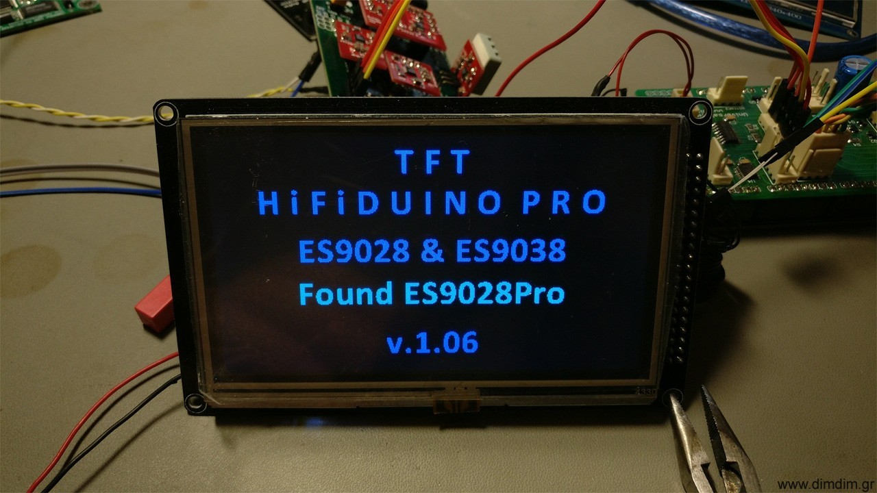
All is here: TFT HiFiDuino Pro Project | Dimdim's Blog
I'm looking forward to receiving feedback from brave builders..
All is here: TFT HiFiDuino Pro Project | Dimdim's Blog
I'm looking forward to receiving feedback from brave builders..
dear dimdim;
really perfect job..I am so excited now... I will make your isolated shild with your help.. thanks you so much.
really perfect job..I am so excited now... I will make your isolated shild with your help.. thanks you so much.
Hi Dimdim looking for some help please.
I am just in the process of making up link cable.
Should I use
pin 1 of shield to 3.3v Vcc of my dac pcb
pin 2 of shield to SDA of my dac pcb
pin 3 ?
pin 4 ?
pin 5 of shield to SCL of dacpcb
pin 6 to GRD of dac pcb.
Do I need to connect any other wires from shield to dac pcb or modify program because you mentioned the GP104 line on buffalos and side car control pin 3 ?.
Thank you for fast postage of shield pcbs and your help Dave.
Attachments
Hi there Dave,
To connect to the DAC you use header I2C_ISOL1.
Your pinout is right, you just need to connect the GPIO4 pin (pin 26) of the 9028/38 to Pin 4 of the I2C_ISOL1 header.
I don't remember you mentioning whether you have access to GPIO4 (pin 26) or not. If you don't, you could use either one of pins 27, 28 or 40 (with some very minor changes to the code). If you have no access to any of those pins, I'll have to do some changes to the code to get it to work. But it is best / way more "elegant" if you use one of these pins.
In your case (DIYINHK ES9038Pro DAC) you don't need to connect pin 3 to anything.
Hi dimdim sorry to keep bothering you I just need a bit of help connecting encoder.
As far as I have worked out for my encoder.
CLK to pin 1 or 2
DT to pin 1 or 2
SW to pin 3
GRD to pin 4
My encoder has a + should I connect a 3.3v supply to this.
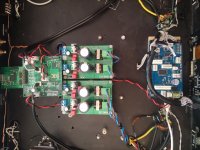
Great news on my dac pcb it has a place for pin 26 of dac chip I can use.
As far as I have worked out for my encoder.
CLK to pin 1 or 2
DT to pin 1 or 2
SW to pin 3
GRD to pin 4
My encoder has a + should I connect a 3.3v supply to this.
Great news on my dac pcb it has a place for pin 26 of dac chip I can use.
Attachments
![20170904_095653[144].jpg](/community/data/attachments/571/571753-8c69d371b7f4ea2dd330b9372cbe4166.jpg?hash=jGnTcbf06i)
I have one such encoder at home, I'll test it tonight and let you know.
Very good news on the pin 26 topic. 🙂
Very good news on the pin 26 topic. 🙂
@dimdim does your code have logic to setup a 9038Pro for synchronous mode in order to bypass all reclocking?
Hi dimdim sorry to keep bothering you I just need a bit of help connecting encoder.
As far as I have worked out for my encoder.
CLK to pin 1 or 2
DT to pin 1 or 2
SW to pin 3
GRD to pin 4
My encoder has a + should I connect a 3.3v supply to this.
Great news on my dac pcb it has a place for pin 26 of dac chip I can use.
OK, I had a look at the encoder. Your pinout is essentially right:
CLK to pin 1
DT to pin 2
SW to pin 3
GRD to pin 4
You should not supply 3.3V to the encoder but you should desolder the two existing 10K resistors on the back of the encoder's pcb.
@dimdim does your code have logic to setup a 9038Pro for synchronous mode in order to bypass all reclocking?
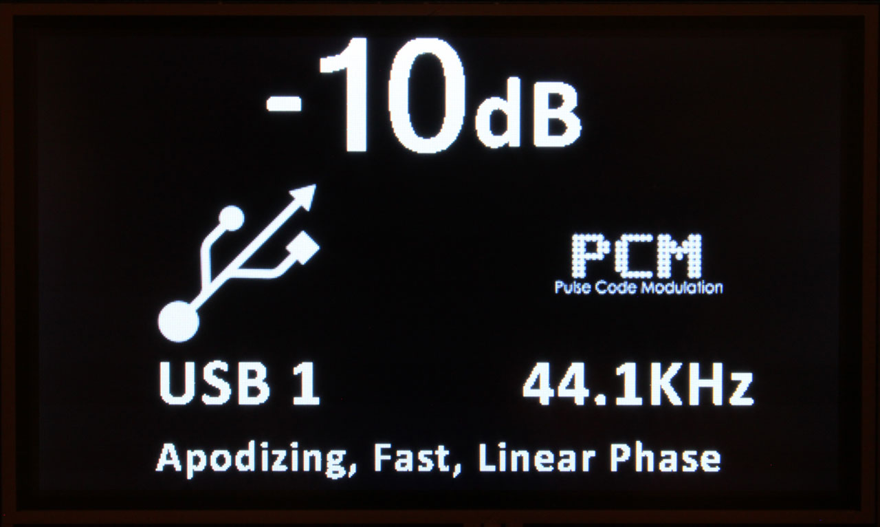
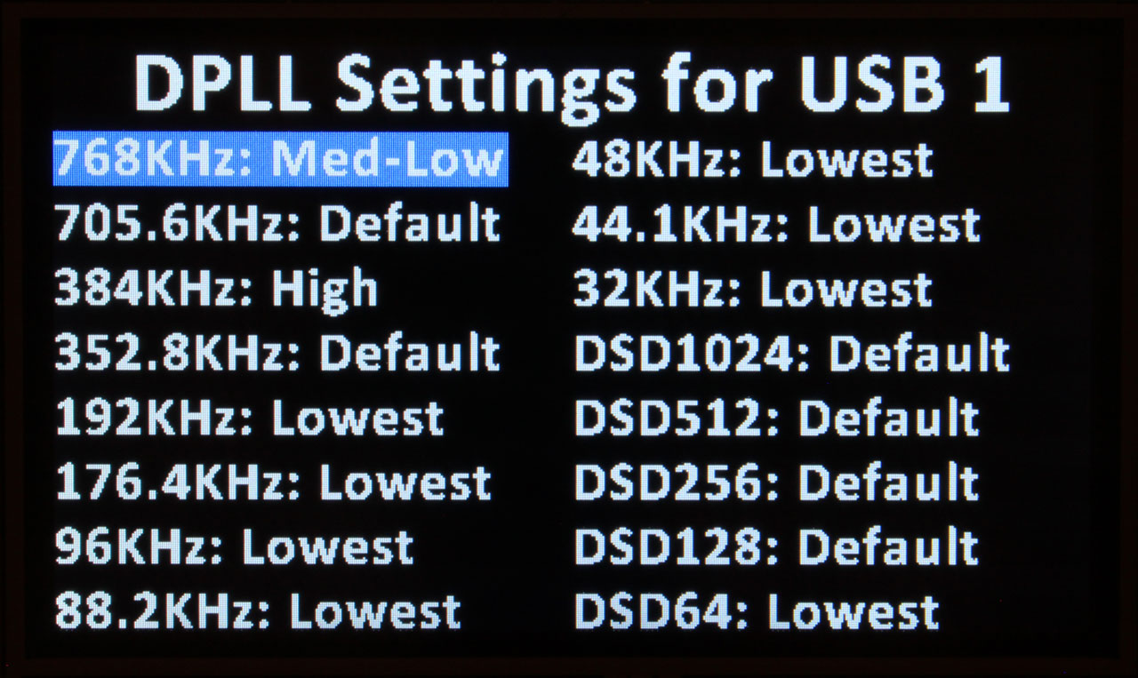
AFAIK you don't need special code to do that - you just supply the right clock according to your material's sampling rate. My code does include provision for disabling the DPLL if one sees a reason to do that.
But the sampling rate calculations will be off since they are dependent on knowing the MCLK. The code could be adapted to take two known oscillator frequencies and do the proper math, but the arduino would need to know which clock you have selected. It could get this info by monitoring the oscillators' enable lines.
Thanks, I have Ian's mcfifo boards and plan on using them with the diyinhk 9038 board but I wasn't sure if I just needed to feed the MCLK to the board somehow or if I had to setup the chip as well.
OK, I had a look at the encoder. Your pinout is essentially right:
CLK to pin 1
DT to pin 2
SW to pin 3
GRD to pin 4
You should not supply 3.3V to the encoder but you should desolder the two existing 10K resistors on the back of the encoder's pcb.
Thank you Dimdim
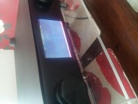
Hi Dimdim really sorry to keep bothering you but this is my files and I am still getting same error.
As you can see it loads UTFT.Arduino(ARM)+ Teensy UTFT_Demon_480x272 demo.
I have to put 3.3v to TFT screen though.
As you can see it loads UTFT.Arduino(ARM)+ Teensy UTFT_Demon_480x272 demo.
I have to put 3.3v to TFT screen though.
Attachments

Last edited:
- Home
- Source & Line
- Digital Line Level
- Buffalo III upgraded with ES9028Pro