Yes, a few years back I'd reached a similar view, but for quite different reasons, for a spherical stylus at least. I figured one might as well use the available VTF budget and spend it on damping, implying lower compliance. Strange how some things converge for all the wrong reasons.......This then leads to the Walton spec for a pickup (as you say SOTA in 1960ish) should be
5cu compliance
less than 1mgm effective tip mass
'well damped'
3g VTF.
Would be good to tie up the loose ends as best we can.Still leaves a hole the test for the damage though and you might be right that he just didn't copy read properly.....
The 1961 article you linked http://www.americanradiohistory.com/Archive-Wireless-World/60s/Wireless-World-1961-08.pdf has some narrative that seems to confirm the author believed the same offending SEM showing damage to be for a single play of Decca SXL2057, 10kHz@5cm/s one channel only, at 2.7g VTF with a stylus 'tip-mass' of 3mg. But I really doubt that.
Much of that WW article waddles about trying to calculate theoretical minimum VTF to track that Decca SXL2057 10kHz@5cm/s rms single channel test track. But the author misses an easy simplification: consider the unmodulated wall where the stylus is meant to just slide up and down a flat 45 deg inclined surface at a velocity of 5cm/s@10kHz !! The author ignores friction (which is wrong IMO, but hey), so let's stick with that for now because we're interested in the condition when the stylus is just left hanging in mid air because the groove wall beneath it has moved away faster than it can accelerate downwards under VTF.
Minimum VTF to satisfy peak downward acceleration and keep the stylus in contact with groove walls works out at 1.34gf for a 3mg tip mass.
Then at 2.7g VTF, as the artricle claims for the SEM, would result in a net downforce of 2.7gf + (1.34gf * sin(ωt)), ie swing between 1.36gf and 4.04gf over a sine cycle at 10kHz. Allowing reasonably for suspension forces, I might just about expect this to trace and track OK with a tail wind.
Still considering the plain unmodulated wall, the normal reaction force to support the stylus would vary between 0.96gf and 2.86gf over a sine cycle at 10kHz.
The key is to look at the SEM of the unmodulated wall which, by the author's criteria, should show no damage. However, there is a deep continous gouge on the unmodulated wall, whose depth modulates somewhat over a sine cycle. IMO, this SEM is more likely to be consistent with extreme VTF loading than stylus inertia force damage.
The second SEM (from the book Bill scanned) for 2.7gf VTF (and 0.6mg) tip-mass indeed shows no damage to the unmodulated wall apparently after 250 plays, and this seems plausible that 2.7gf was the VTF, IMO. My opinion is that high VTF might well have been used for the 'damaged' SEM, acknowledging that is not what the WW article reports.
A few more loose ends: Figures 9 and 10 of the WW article seem not to have the same magnification, and so appears not to be an image of the same section of the waveshape. The area of damage in fig 9 is not shown on fig 10. Figures 5 and 6 appear to show optical images of groove damage to the modulated wall at points that dont corresond to peak acceleration.
A thesis for explaining the 'damaged' SEM is that a cartridge incapable of tracking the test disc was operated at high VTF, and bounced its way along the leading edges of modulated wall elevations, whilst cutting its own gouge in the unmodulated wall. In this way, the stylus path would have been phase shifted from the original modulation, and the gouge on the unmodulated wall reflects this. Personally, I think this explanation better fits the image........
If this thesis were true, it might perhaps be significant in unfathoming the origins of common lores and misunderstandings that have shaped the industry and behaviours/choices of consumers for decades ??
LD
Last edited:
I would totally agree were it not for the name check of the elusive Dr.Chippindale and his 'unique process'. Maybe i'm too trusting of early 60's scientists but I want to find more.
A thesis for explaining the 'damaged' SEM is that a cartridge incapable of tracking the test disc was operated at high VTF, and bounced its way along the leading edges of modulated wall elevations, whilst cutting its own gouge in the unmodulated wall. In this way, the stylus path would have been phase shifted from the original modulation, and the gouge on the unmodulated wall reflects this. Personally, I think this explanation better fits the image........
LD
This seems perfectly plausible to me as being the only logical explanation for what we see.
Hans
Just to make sure I am reading the plates the same as you are have marked one up.
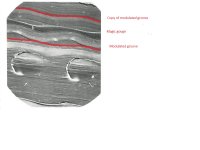
The top red line is the 'copy' of the modulated groove. The lower one the best line I can find through the actual modulated groove using a trackpad. Clearly not the same section of groove, but close enough. The 'magic gouge' is the bit none of us can quite work out and at the bottom is the damage caused as the stylus, weighted down with 2 guineas slams into the wall.
If you look between the two dents in the modulated wall you can see that the gouge doesn't follow the modulation and instead mistracks, possibly catching a bit of air as it does ready to slam back down and dent the wall again. (note still clueless as to how this was captured)
At least that is how it looks to me. Heroic effort to get it to misbehave that badly on a mild modulation...
Attachments
Bill,Just to make sure I am reading the plates the same as you are have marked one up.
The top red line is the 'copy' of the modulated groove. The lower one the best line I can find through the actual modulated groove using a trackpad. Clearly not the same section of groove, but close enough. The 'magic gouge' is the bit none of us can quite work out and at the bottom is the damage caused as the stylus, weighted down with 2 guineas slams into the wall.
If you look between the two dents in the modulated wall you can see that the gouge doesn't follow the modulation and instead mistracks, possibly catching a bit of air as it does ready to slam back down and dent the wall again. (note still clueless as to how this was captured)
At least that is how it looks to me. Heroic effort to get it to misbehave that badly on a mild modulation...
Just as LD has suggested, the gouge is almost 180 degrees out of phase, as to be expected from a second order mass-spring system no longer being able to follow the "road".
Compare it to the movements of a wheel from a car with a broken shock absorber, following the road bumps 180 degrees out of phase.
Hans
Yes, was just checking we were all looking at it and seeing the same thing. There was a major tank slapper going on. just off to scan the missing page.
Edit: missing page added. Low res but its only the text you need and I it's only for completeness.
Edit: missing page added. Low res but its only the text you need and I it's only for completeness.
Attachments
Last edited:
Thanks Bill. That answers a few questions I had, which may not be the questions others had.
I was wondering if we couldn't do this ourselves (DIY) with an optical microscope. Many of the micrographs found around the 'net are at 500x-1000x, certainly within our abilities. The SEM in the book is 2300X and might be better at showing detail, but how much could we see with optical means?
I was wondering if we couldn't do this ourselves (DIY) with an optical microscope. Many of the micrographs found around the 'net are at 500x-1000x, certainly within our abilities. The SEM in the book is 2300X and might be better at showing detail, but how much could we see with optical means?
well revisiting plate 3 it shows it is the same picture as plate 4 but optical, so that strengthens the gouge being real. With an adjustable z stage and modern software you can do rather well. Let me PM someone over on VE who does some pretty amazing stylus images to see what he reckons. If you have a DSLR its only a few hundred more to get the other bits to get you going.
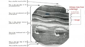
Hi Bill, thanks for that and the extra scan. I attached my own mark up of that plate, leaving in place the labels I think the author has correct, and adding my own in red for what I believe we are actually looking at.Just to make sure I am reading the plates the same as you are have marked one up.
The top red line is the 'copy' of the modulated groove. The lower one the best line I can find through the actual modulated groove using a trackpad. Clearly not the same section of groove, but close enough. The 'magic gouge' is the bit none of us can quite work out and at the bottom is the damage caused as the stylus, weighted down with 2 guineas slams into the wall.
If you look between the two dents in the modulated wall you can see that the gouge doesn't follow the modulation and instead mistracks, possibly catching a bit of air as it does ready to slam back down and dent the wall again. (note still clueless as to how this was captured)
At least that is how it looks to me. Heroic effort to get it to misbehave that badly on a mild modulation...
If one wishes to see the true locus of the groove modulation as cut, vertically it is the lines of the witness marks and laterally it is the boundary of the groove base and the modulated wall (same as the boundary of the record top and the modulated wall). Then it's clear that the locus of the gouge has a phase offset - as you say it appears to 'catch air' at least on the modulated side, and lands on the elevated parts of the modulated wall.
As to how the SEM image was made, I think the record must have been dissected and a section small enough to fit in the SEM chamber prepared. Before placing in the SEM, the sample has to be sputter coated with a conductive layer, such as carbon or gold - but this must be after the playback when the sample has already been dissected.
There are so few SEM images of grooves in the public domain that images such as these might have been very influencial in terms of public perception. All the more reason that correct interpretation was made, whereas on the face of it, that might well not have been the case, unfortunately.........
LD
Attachments
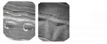
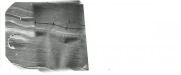
I noted something else this afternoon and need to do a bit of scaling. Plate 4 (250 plays) also shows the beginnings of a gouge where the stylus has been sliding up and down the wall. I need to rescale and put them side by side for comparison, but I believe that is the conclusive proof that you are right.
Bill,
Just as LD has suggested, the gouge is almost 180 degrees out of phase, as to be expected from a second order mass-spring system no longer being able to follow the "road".
Compare it to the movements of a wheel from a car with a broken shock absorber, following the road bumps 180 degrees out of phase.
Hans
Better example being a car with an ineptly designed suspension oscillation frequency. No broken parts required 😉
YES.... Car suspension Does encompass that.
Some makers being far more adept than others in dealing effectively with it.
Back in the 60's it was fairly commonly accepted amongst Audio Weenies that an LP was audibly inferior from new by it's 6th/8th playback.
Other point is; these are cheap expendable plastic pressing/recordings. Often bought at a thrift shop for 1$.
Something ..will.. eat them, sooner or later 😱
May be the faint sinusoidal wave on unmodulated groove was made while making master.
Regards.
Regards.
Pardon me. I mean while cutting the master. Probably at that time record wear may not be the goal to have one channel modulated.
Well, we've pretty well busted that myth from the well conducted and controlled tests here on the thread.Back in the 60's it was fairly commonly accepted amongst Audio Weenies that an LP was audibly inferior from new by it's 6th/8th playback.
There's even some circumstances under which playback progressively improved......(!) however the main 150 playback test showed little degradation, and I'll post the full analysis as soon as things on the forum stop being so interesting and busy 😉
Meantime, here's an attempt at creating a composite image of the 'damaged'/'undamaged' SEM plates Bill posted. If the conditions for the 250 playback test are as described, right of the image, it supports the idea that polish of surface texture might happen after multiple playbacks IMO. Also supports that unmodulated wall contact was similar between 'damaged' and 'undamaged' images, and that the significant difference might have been excessive VTF based upon the depth and continuity of the gouge, IMO.
LD
Attachments
Last edited:
I still don't understand that gouge. It looks like it was made with a sharp tip, a tip much sharper than a stylus would be. Normally the stylus is too large to get to the bottom of the groove.
The way the image flattens the groove, it's a little difficult to tell what the gouge is like. Is it up the wall a few microns from the bottom of the groove? Would something sharp be needed to plow a row like that, or is it not as it appears?
The way the image flattens the groove, it's a little difficult to tell what the gouge is like. Is it up the wall a few microns from the bottom of the groove? Would something sharp be needed to plow a row like that, or is it not as it appears?
If you think of the contact blob of a spherical tip sliding up and down the unmodulated wall then it makes sense. for the 250 plays case it's smoothed out its path, like the tracks you see on any two sliding surfaces after a number of operations. For the damage case its because we think VTF was well above plastic deformation threshold and the contact patch 'dug in'.
I've been mulling cartridge design again and need to go on a trawl for Grado patents. Now admittedly the following quote has been embellished by marketing, but suggests Joe and the people who succeeded him were on the same page as LD wrt trasmission lines.
I've been mulling cartridge design again and need to go on a trawl for Grado patents. Now admittedly the following quote has been embellished by marketing, but suggests Joe and the people who succeeded him were on the same page as LD wrt trasmission lines.
Now I've never really considered Grado carts at all, but I do want to see what they actually patented to see if its any different from the Shure telescopics with black goop on. Would be nice to discover that Grado had actually worked it out...OPTIMIZED TRANSMISSION LINE (OTL) STYLUS/CANTILEVER
Grado's OTL provides an ideal transfer of the signal from point to point, e.g., stylus to cantilever to magnet to coils, etc. This has been achieved by eliminating resonance at each of these key junctions. The transmission line cantilever consists of separate sections that are telescoped into each other. All sections are made of different alloys, some sections hollow, other sections solid. These sections are bonded together with materials that act as dampers, and are coated with a black proprietary material which controls and absorbs resonances that travel on the surface of the cantilever (known as skin effects). The OTL stylus/cantilever design will make your records sound quieter, improve the height, width, and depth of the soundstage, and offer more detail than previously obtainable. Cartridge Holography does exist...and that is what GradoÕs OTL technology is all about, more performance.
It's just been pointed out to me that the 2 fine volumes of AES anthologies on disk recording and playback are now available as pdf download rather than paper. TOCs below
http://www.aes.org/publications/anthologies/downloads/jaes_disk-anthology-1.pdf
http://www.aes.org/publications/anthologies/downloads/jaes_disk-anthology-2.pdf
1000 pages of good stuff from the good old days for $80 . I think I will put that on my xmas list 🙂
http://www.aes.org/publications/anthologies/downloads/jaes_disk-anthology-1.pdf
http://www.aes.org/publications/anthologies/downloads/jaes_disk-anthology-2.pdf
1000 pages of good stuff from the good old days for $80 . I think I will put that on my xmas list 🙂

- Home
- Source & Line
- Analogue Source
- mechanical resonance in MMs