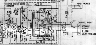
Added my own asymmetric mod.
I'll do my own listening test later. One channel is stock and the other is modified.
While I was at it, checked the noise at output, getting less than 100uV (averaging around 30uV to 50uV), based on the fact I have 4 times more capacitance than stock this seems correct.
I'll do my own listening test later. One channel is stock and the other is modified.
While I was at it, checked the noise at output, getting less than 100uV (averaging around 30uV to 50uV), based on the fact I have 4 times more capacitance than stock this seems correct.
Guess. Haha.
I'm not sure if this is accurate or not but this is how I put blind faith in Fluke.
First I measured the noise floor of my Fluke meter which measured 320uV.
I then measured the amp which was below the noise floor of 320uV.
I then used a function on the meter called RELATIVE, this basically zeroes out the noise floor (Blind faith here) and then remeasured the amp and got around 50uV, let's call it less than 100uV, I always prefer understating results.
I might give Fluke a call to check whether this a reliable way to measure noise.
The good news is I should have a brand new Keysight Audio Analyzer to play with in about a month, when it arrives I'll see what that can do.
If you're instrumentation is not great you can measure noise by feeding the output into a low noise amplifier with say a gain of 100, then divide answer by 100, eg 10mV/100 = 100uV
Thanks for your reply , i have an Fluke 287 , i will see if it has the relative function like your .
.
.
Decided to measure capacitance across primary and secondary windings of a brand new set of transformers, got a figure around 11nF datasheet says 18nF.
Has anyone else measured this?
Edit: Nothing wrong with my meter as I measured a 4nF cap and it measure correctly.
Has anyone else measured this?
Edit: Nothing wrong with my meter as I measured a 4nF cap and it measure correctly.
Last edited:
Yeah, brand new straight out of the box.Did you just attach the capacitance meter to the disconnected transformer terminals?
Just want to confirm if someone else gets this figure.
I measured 2 different JT-123-FLCF units, the version with wire leads. Winding to winding capacitance at 1KHz is about 10.5 nF in both of them. The datasheet claims 24.5 nF.
Looking at the current datasheet for JT-123-FLPCH, claimed capacitance measurements are:
winding to winding, 1 KHz: 24nF
winding to frame, 1 KHz: 35 pF
Looking at the current datasheet for JT-123-FLPCH, claimed capacitance measurements are:
winding to winding, 1 KHz: 24nF
winding to frame, 1 KHz: 35 pF
if Mithrandir chose them for task , I'm just going to blindly accept them
just as one thing less to check , knowing in which circuit they're good
there are few other things about every xformer more important to know , than winding capacitance
just as one thing less to check , knowing in which circuit they're good
there are few other things about every xformer more important to know , than winding capacitance
I'm not being critical, just wanting to be certain about the value.
I'm simulating versions of this circuit with some added tricks and different devices, so being able to model it correctly is important to me that's all.
I'm simulating versions of this circuit with some added tricks and different devices, so being able to model it correctly is important to me that's all.
in that case , do not let me spoiling your fun 🙂
while you at it , measure bandwidth and saturation level with intended load
while you at it , measure bandwidth and saturation level with intended load
it's great that The Funny One is un-dusting some things for us , usually memory-challenged audiophools
Usually I am creating from whole cloth, later finding that someone else
has already signed the guest book.
- Home
- Amplifiers
- Pass Labs
- F6 Amplifier

