Hi,
I am trying to build a speaker with the SP Acoustics SB13PFC25-04 woofer and Dayton ND25FW-4 tweeter. The goal was to keep the components below $200 for the speakers not including the enclosure.
By the help of one of the forum's member - Mayuri i've come into a crossover design and enclosure that was fixed to ~15liter
One problem we saw is that the total impedance is relatively low - ~2Ohm which I should increase (it will be connected to a tube amp 10W/ch). I've read that adding in series a resistor will help increase the impedance but will add some distortion ?!
Any additional comments and/or recommendations will be welcomed.
* I have no tools to measure therefore all the design will be based solely on simulation and feedback
Thanks.
Last edited:
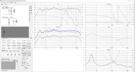
Your XO filter is basically more or less completely in a need of a redesign. Load up the frd and zma files and I'll see what I can do. 47 uf in shunt to woofer with a 4 ohm driver!


Here are frd and zma files
Lojzek, can you explain for a novice "47 uf in shunt to woofer with a 4 ohm driver!"
burnett, nice enclosure. Can you share which components did you use?
View attachment frd_zma.zip
Lojzek, can you explain for a novice "47 uf in shunt to woofer with a 4 ohm driver!"
burnett, nice enclosure. Can you share which components did you use?
View attachment frd_zma.zip
Here are frd and zma files
Lojzek, can you explain for a novice "47 uf in shunt to woofer with a 4 ohm driver!"
He was referring to your crossover which shows 47uF cap parallel to woofer.
Seems excessive, something closer to 10uF is usually seen in that position.
Kind regards
Marko
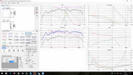
I've built something very similar:
View attachment 620756
Here's a screenshot from VituixCAD:
View attachment 620757
Here is your design with my components.
Attachments
Thanks Marko, fellow countryman, always good to see one here.
sagi, let me see if I can muster one quick sim.
sagi, let me see if I can muster one quick sim.
Unfortunalety I don't have the time and will to do the sim from the scratch but I'll give you some hints to improve it. Lose the resistor in tweeter circuit that just has nothing to do there and pad the tweeter with a simple series resistance before the XO. Reduce the number of components to 3rd order tweeter if a typical flat baffle (not angled) is where the units will rest. Introduce the baffle step response to your simulation for it appears you haven't included one yet. Reduce unnecessary large caps in woofer circuit and increase inductance value to keep impedance benign. Inductance in tweeter circuit goes from about 0,1-0,56 mH for XO points in the usual range. 1,8 mH is excessive and pointless. Good luck.
Unfortunalety I don't have the time and will to do the sim from the scratch but I'll give you some hints to improve it. Lose the resistor in tweeter circuit that just has nothing to do there and pad the tweeter with a simple series resistance before the XO. Reduce the number of components to 3rd order tweeter if a typical flat baffle (not angled) is where the units will rest. Introduce the baffle step response to your simulation for it appears you haven't included one yet. Reduce unnecessary large caps in woofer circuit and increase inductance value to keep impedance benign. Inductance in tweeter circuit goes from about 0,1-0,56 mH for XO points in the usual range. 1,8 mH is excessive and pointless. Good luck.
Thanks, I will work on that.
I use that woofer in a commercial design. What crossover point do you want? We have it crossed at 2.1Khz on a floorstanding unit and 2.6Khz on a bookshelf. You have to add a gasket to it, the built in foam one does little to prevent leakage and at higher levels it becomes noticeable. Room window sealers (those with sticky stuff on them) work great.
Last edited:
I was thinking ~2kHz for my bookshelf designI use that woofer in a commercial design. What crossover point do you want? We have it crossed at 2.1Khz on a floorstanding unit and 2.6Khz on a bookshelf. You have to add a gasket to it, the built in foam one does little to prevent leakage and at higher levels it becomes noticeable. Room window sealers (those with sticky stuff on them) work great.
Sagi
I was thinking ~2kHz for my bookshelf design
Sagi
In my opinion 2.6kHz would be better for your tweeter, Fs is 1350Hz.
They even suggest that in datasheet.
Kind regards
Marko
Attachments
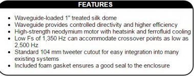
In my opinion 2.6kHz would be better for your tweeter, Fs is 1350Hz.
They even suggest that in datasheet.
Kind regards
Marko
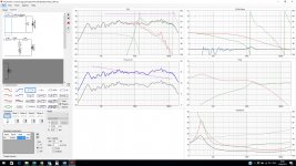
Here is a new version with cross at ~2400Hz
Attachments
Are you using some kind of crossover calculator?
Unfortunately that doesn't work.
A few things that look questionalbe in that crossover:
- a resistor in series to the woofer (4,7R)?
- 39µF parallel to the woofer look still way too big.
- 120µF on the tweeter doesn't do anything - would also be very expensive.
- that bump at the resonance frequency of the tweeter
I am not using crossover calculator rather using the VituxCAD and tweak it visually.Are you using some kind of crossover calculator?
Unfortunately that doesn't work.
A few things that look questionalbe in that crossover:
- a resistor in series to the woofer (4,7R)?
- 39µF parallel to the woofer look still way too big.
- 120µF on the tweeter doesn't do anything - would also be very expensive.
- that bump at the resonance frequency of the tweeter
Are you suggesting to move to a calculator for the preliminary stage ?
Sagi
Sagi,
First of all forget about VituxCad for now🙂
I found this 2-way design with your woofer, but a different tweeter.
2 Vejs Rabu
In your place I would copy that design completely which means buying new tweeters, that would be the best solution.
If you don't want to buy new tweeters, which is a bad idea, I would still copy that design completely and play with value of R1 in series with the tweeter, 10 ohm would be a good start.
Kind regards
Marko
Attachments

Try this one and see how you like it - 1.1mH on the woofer with a parallel notch of 3R6 - 3.3uF - 0.21mH (0R6 for the coil). This will negate the light peak which is noticeable (which delivers very paperish sound with the right material), and produce an almost perfect LR2 if you have done your measurements well. The crossover I suggest you try is designed for close to wall placement. If you`re going for stands, they will sound thin and you`d need more BSC (so increase coil). The woofer is pretty clean and can do easily a 2nd order.
Flush mounting it can be a problem because of the frame, easiest for DIY is to buy 4mm MDF, draw the frame on it with a pencil and then use a jigsaw to cut it and then glue it to the main baffle.
You can offset the tweeter to reduce its diffraction peak and try a 3rd order slope with it. They do sound better crossed lower, at around 2.1Khz, but with this tweeter its better to aim for 2.6Khz+.
Last edited:
Try this one and see how you like it - 1.1mH on the woofer with a parallel notch of 3R6 - 3.3uF - 0.21mH (0R6 for the coil). This will negate the light peak which is noticeable (which delivers very paperish sound with the right material), and produce an almost perfect LR2 if you have done your measurements well. The crossover I suggest you try is designed for close to wall placement. If you`re going for stands, they will sound thin and you`d need more BSC (so increase coil). The woofer is pretty clean and can do easily a 2nd order.
Flush mounting it can be a problem because of the frame, easiest for DIY is to buy 4mm MDF, draw the frame on it with a pencil and then use a jigsaw to cut it and then glue it to the main baffle.
You can offset the tweeter to reduce its diffraction peak and try a 3rd order slope with it. They do sound better crossed lower, at around 2.1Khz, but with this tweeter its better to aim for 2.6Khz+.
Which one you referring to? mkusan or my last simulation?
Doesn`t matter really, its a straight forward crossover. If you look at mkusan`s simulation, instead fo 1.8mH you can go down to 1.1mH and instead of the C-R parallel junction - you can try the L-C-R one I suggested above. For the tweeter I cannot help I`m afraid, never had one of those around.
- Home
- Loudspeakers
- Multi-Way
- Speakers based on 5in-SB13PFC25-04 & Dayton ND25FW-4