Current limiting is turned off. Power supply is in constant voltage mode,
not constant current mode.
If you're using a lab supply, it may still be unhappy with the amplifier.
Try a different supply to be sure.
If you're using a lab supply, it may still be unhappy with the amplifier.
Try a different supply to be sure.
I am building another supply, just simple rectifier with RC filters. Not done yet. But why would the amplifier be unhappy with a large, linear regulated supply?
why would the amplifier be unhappy with a large, linear regulated supply?
There's no guarantee that the lab supply (a feedback amplifier) is adequate
for the demands of your circuit. Many lab supplies have poor AC response.
https://pdfs.semanticscholar.org/9291/1aee33f17f0fe3cd3a04b925ab0adb307ed6.pdf
http://www.ti.com/lit/an/snoa507/snoa507.pdf
Last edited:
There's no guarantee that the lab supply (a feedback amplifier) is adequate
for the demands of your circuit. Many lab supplies have poor AC response.
https://pdfs.semanticscholar.org/9291/1aee33f17f0fe3cd3a04b925ab0adb307ed6.pdf
http://www.ti.com/lit/an/snoa507/snoa507.pdf
If the power supply I am using had high source / sink impedance at 1 kHz, wouldn't you expect the problems to show up on both rails, especially since the AC current through the positive 18 V rail is 5 times greater than the negative rail? And wouldn't you expect it to show up in a constant fashion, not dependent on amplifier output power level?
I will try the unregulated supply once it's done. I'm waiting on a PCB.
wouldn't you expect it to show up in a constant fashion, not dependent on amplifier output power level?
Large signal response is typically significantly different (usually worse) from the small signal response
in a regulated supply. The best test here is a different supply.
I agree with rayma. There is nothing that can supply instantaneous current like a capacitor. Not even a lead-acid battery.Large signal response is typically significantly different (usually worse) from the small signal response
in a regulated supply. The best test here is a different supply.
A lot of people think that lab power supplies are the be-all and end-all. They are really just conveniently adjustable. As reyma mentioned, their feedback loops are sluggish.
A lot of people think that lab power supplies are the be-all and end-all. They are really just
conveniently adjustable. As reyma mentioned, their feedback loops are sluggish.
There are special lab supplies that do have fast response, just not the ones most people have.
For example, these have around 10kHz bandwidth and are actually 4 quadrant power op amps.
KEPCO, INC.: DC POWER SUPPLIES/DC POWER SUPPLY: BIPOLAR, OPERATIONAL AMPLIFIER, RACK MOUNT OR BENCH, GPIB SCPI ANALOG PROGRAMMABLE, DIGITAL, LINEAR - SERIES BOP
Last edited:
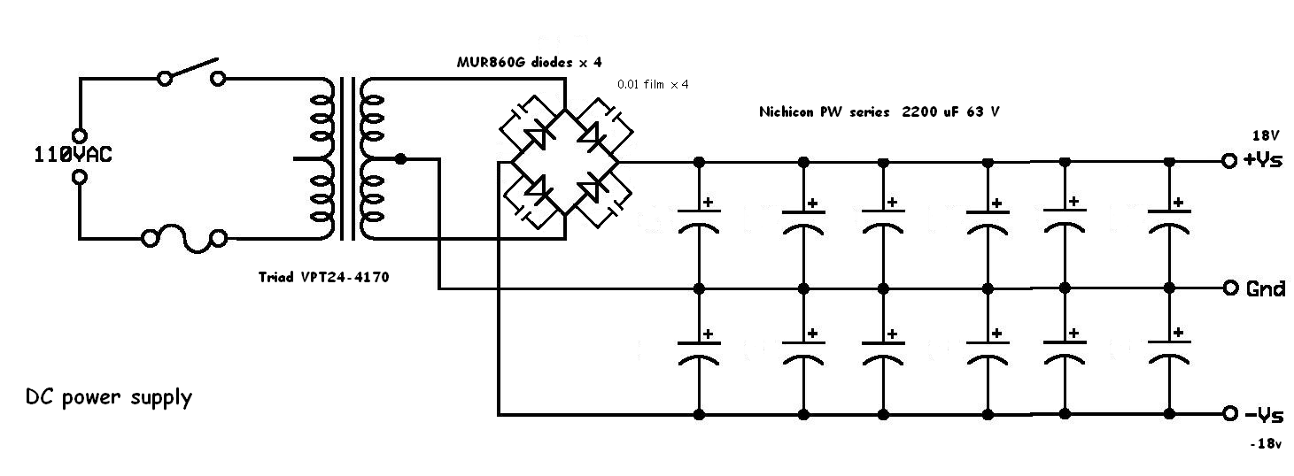
OK, so my PCB came and I built the unregulated power supply, here's the schematic. The transformer secondary is capable of 8.5 amps output. The single Aleph-M amplifier board draws just about 2 amps off each rail.
There is a 1 ohm / 10 watt noninductive resistor in series with the + rail output and one in series with the - rail output - the current sensing resistors are in series between the output of the power supply rails and the + and - DC rail inputs of the amplifier board, which is the only place they can be to measure the rail current. Surely I don't have to draw those on here, do I? 🙂
And here's the current waveform on the negative rail with the input signal voltage level adjusted so that the waveform just begins to distort...
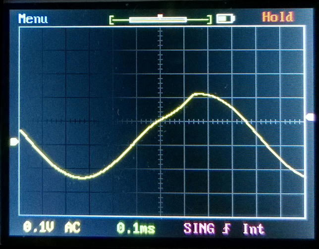
...and then I backed off the 1 KHz sine input level just a tiny bit so the negative rail current waveform now looks sinusoidal
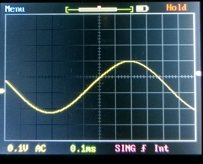
Here is the positive rail current waveform, nice sine shape
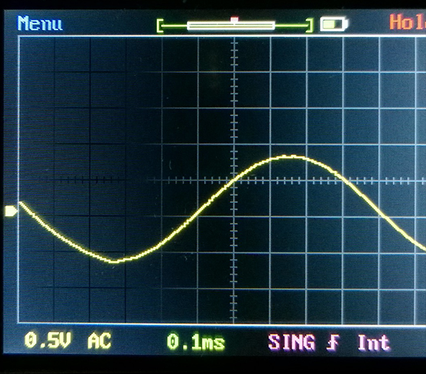
And here is the output waveform, which is just under 15 volts peak-to-peak
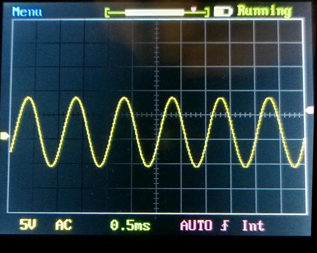
15 volts p-p is 5.3 volts RMS; 5.3 volts RMS into 8 ohm load is 3.5 watts
This is essentially the same result as the regulated lab power supply. So, the premise that the lab power supply was causing some kind of problem seems not to be true.
I have not yet changed the resistor as suggested by Nelson in an earlier post, which may give me more output in Class A - more output power before either the negative or positive rail current waveform begins to distort, which he seemed to say was an indication of leaving class A. [ He said "Try a 2.2 Kohm resistor on the Gate of the PNP instead of the 1.5K."]
There is a 1 ohm / 10 watt noninductive resistor in series with the + rail output and one in series with the - rail output - the current sensing resistors are in series between the output of the power supply rails and the + and - DC rail inputs of the amplifier board, which is the only place they can be to measure the rail current. Surely I don't have to draw those on here, do I? 🙂
And here's the current waveform on the negative rail with the input signal voltage level adjusted so that the waveform just begins to distort...
...and then I backed off the 1 KHz sine input level just a tiny bit so the negative rail current waveform now looks sinusoidal
Here is the positive rail current waveform, nice sine shape
And here is the output waveform, which is just under 15 volts peak-to-peak
15 volts p-p is 5.3 volts RMS; 5.3 volts RMS into 8 ohm load is 3.5 watts
This is essentially the same result as the regulated lab power supply. So, the premise that the lab power supply was causing some kind of problem seems not to be true.
I have not yet changed the resistor as suggested by Nelson in an earlier post, which may give me more output in Class A - more output power before either the negative or positive rail current waveform begins to distort, which he seemed to say was an indication of leaving class A. [ He said "Try a 2.2 Kohm resistor on the Gate of the PNP instead of the 1.5K."]
Last edited:
2.2 k modification as sugged by Nelson
Mr. Pass said, "Since you have a healthy bias current, it is possibly too much gain in the Aleph current source. Try a 2.2 Kohm resistor on the Gate of the PNP instead of the 1.5K."
(I assume he meant BASE not GATE of the BC550C PNP transistor, as bipolar transistors don't have gates.... he's been working too long with FETs hahahaha)
Here's the modification he suggested
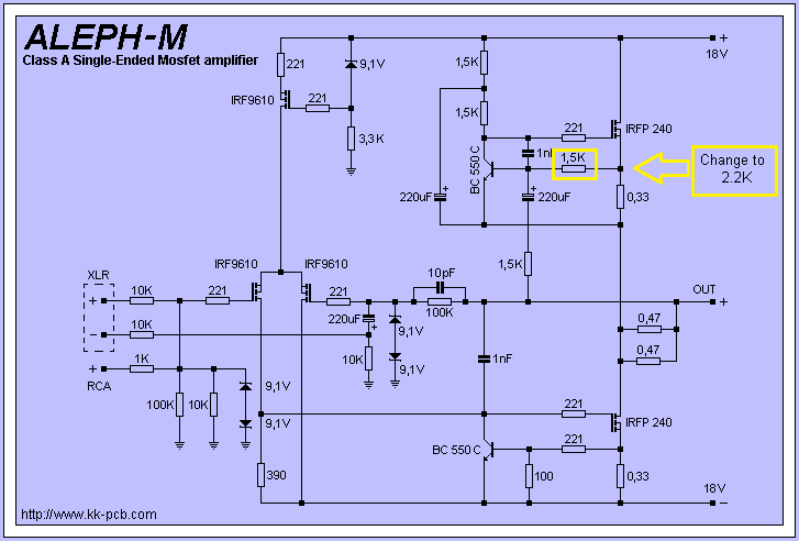
So, I changed that 1.5 K resistor to 2.2 K.
Now, adjusting the level of the 1 KHz input signal until the negative rail current waveform JUST starts to depart from a perfect sine wave*, (which occurred at 0.54 V RMS input) here's the output of the amplifier:
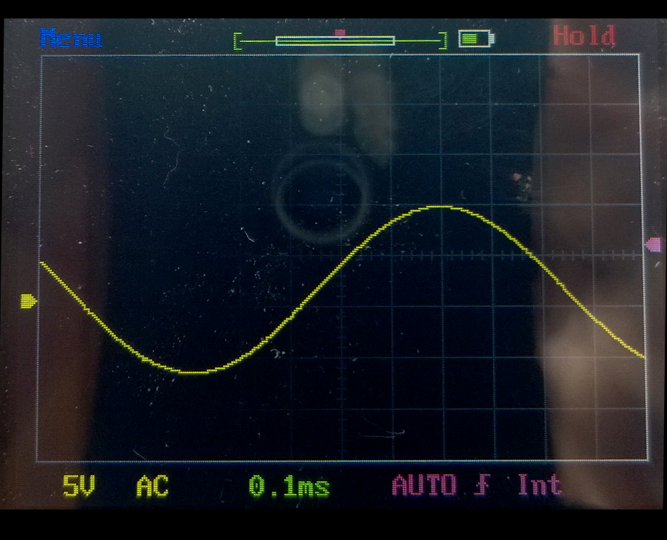
I read that to be 17 volts p-p, which is 6.01 V RMS, which is 4.5 watts into 8 ohms, a 28% increase over the power level I saw with the 1.5k resistor.
Interesting.
==========================================
Nelson said that departure from a good sine wave of either the negative rail current waveform or the positive rail current waveform indicates a departure from class A. In the earlier tests, I saw that the negative rail current waveform started to depart from sinusoidality earlier - at lower signal input levels- than the positive rail current waveform, so distortion in the negative rail current waveform is my "indicator" or departure from class A operation.
Mr. Pass said, "Since you have a healthy bias current, it is possibly too much gain in the Aleph current source. Try a 2.2 Kohm resistor on the Gate of the PNP instead of the 1.5K."
(I assume he meant BASE not GATE of the BC550C PNP transistor, as bipolar transistors don't have gates.... he's been working too long with FETs hahahaha)
Here's the modification he suggested
So, I changed that 1.5 K resistor to 2.2 K.
Now, adjusting the level of the 1 KHz input signal until the negative rail current waveform JUST starts to depart from a perfect sine wave*, (which occurred at 0.54 V RMS input) here's the output of the amplifier:
I read that to be 17 volts p-p, which is 6.01 V RMS, which is 4.5 watts into 8 ohms, a 28% increase over the power level I saw with the 1.5k resistor.
Interesting.
==========================================
Nelson said that departure from a good sine wave of either the negative rail current waveform or the positive rail current waveform indicates a departure from class A. In the earlier tests, I saw that the negative rail current waveform started to depart from sinusoidality earlier - at lower signal input levels- than the positive rail current waveform, so distortion in the negative rail current waveform is my "indicator" or departure from class A operation.
Hmmm
OK doing as you suggest....
the 1 KHz input level where the negative rail current waveform almost begins to show distortion is 0.24 V RMS, here's the output waveform across the 8 ohm noninductive resistor
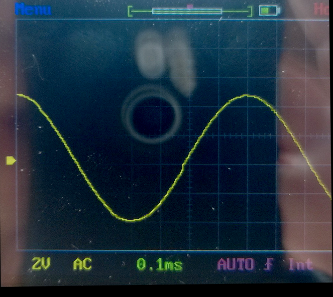
Note this output waveform is shown on a 2 volt / division scale, whereas the earlier ones had to use a 5 volt / div scale.
P-P voltage here is 8.8 volts, which is 3.11 V RMS, for 1.2 watts into the 8-ohm load, or 65% less power that with a 1.5k resistor in that location.
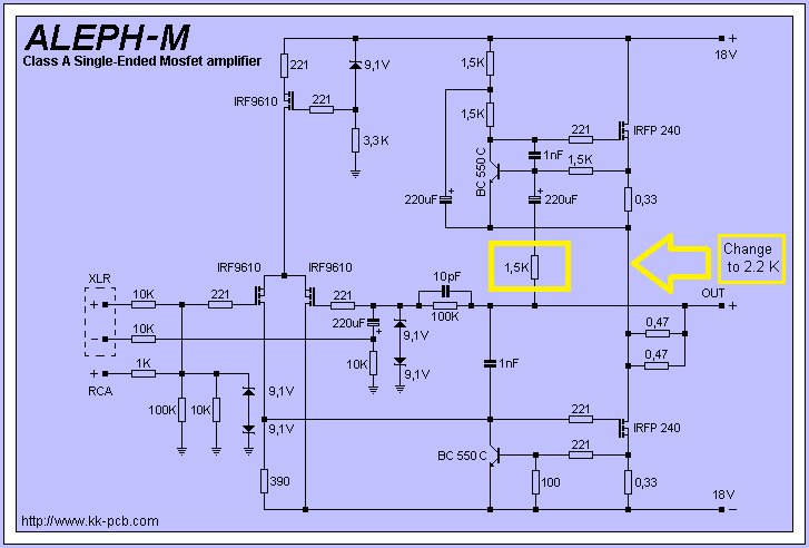
Not that one, the lower 1k5 resistor in series with the 220uF cap.
OK doing as you suggest....
the 1 KHz input level where the negative rail current waveform almost begins to show distortion is 0.24 V RMS, here's the output waveform across the 8 ohm noninductive resistor
Note this output waveform is shown on a 2 volt / division scale, whereas the earlier ones had to use a 5 volt / div scale.
P-P voltage here is 8.8 volts, which is 3.11 V RMS, for 1.2 watts into the 8-ohm load, or 65% less power that with a 1.5k resistor in that location.
I can't understand what you are doing. Anyway, connect 8 ohms load rsesitor on out, then conect , 100mV / 1kHz at input. When aleph ccs current gain is set as it shoul be, then you have the same AC voltage amplitude on the both, uper and lower mosfet source resistor - the 0.33 ohm resistor in the schematic. With chsnging that 1k5 value, you change the ccs current gain and balance between AC voltages across the 0.33 resistors.
I can't understand what you are doing.
Well, you could read the whole thread, everything is explained. But to save you that effort, I will summarize.
I have some Aleph-M PCB's laying around that I bought a few years back and never used. I decided to build two of them into an Aleph-M stereo amp.
When I came to design the power supply, I was struggling to mentally "see" what kind of audio-frequency sink / source current flows would be occurring on the + and - rails. (This is important to know when thinking about the power supply source / sink impedance.)
So, I decided to MEASURE any AC current flow on the - and + power supply rails, using the setup below:
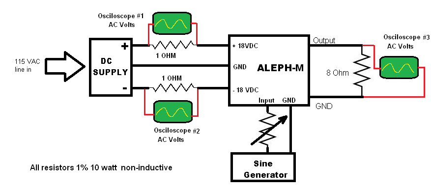
The 1 ohm resistors in series with the DC rails act as current sensing elements; using an oscilloscope to measure the voltage drop across these resistors gives a picture of the AC current element on these rails.
When I adjusted the 1 KHZ sine input to just below clipping as shown on oscilloscope #3 measuring the output across the 9-ohm load, I saw the following waveform on oscilloscope #1 looking at the current in the positive rail

And I saw this waveform on oscilloscope #2 which shows the current flowing in the negative rail
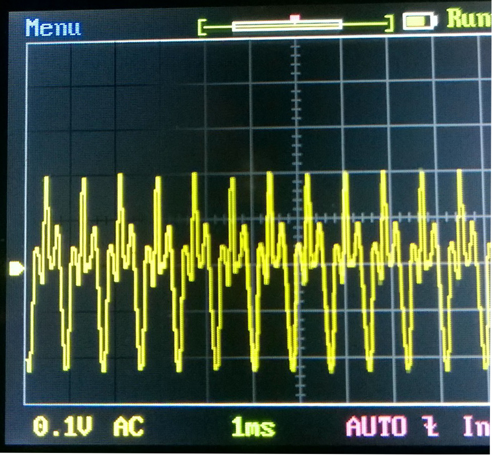
Nelson Pass, the designer of the Aleph-M circuit, looked at these waveforms and said,
"Looks like you have left Class A on that waveform. Current through both rails should show a sine wave, perhaps with some
measure of distortion, but one of your waveforms does not."
measure of distortion, but one of your waveforms does not."
So, OK, I had driven the amplifier to just under clipping- about 14 watts into the 8 ohm load- but this was beyond class A.
Next, I reduced the input signal amplitude until both oscilloscope 1 and 2 showed a nice sine wave,
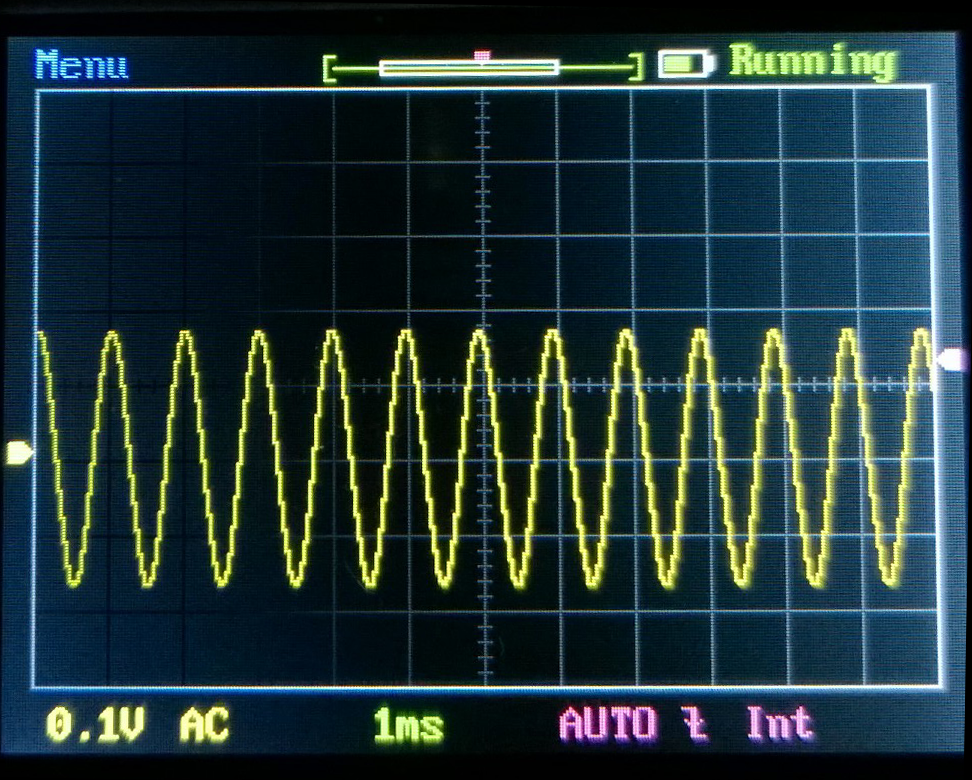
Since I had to reduce the input signal amplitude to bring both rails AC currents into nice sine waves, obviously I would now have less power output from the amplifier. Measuring the voltage across the 8 ohm load with Oscilloscope #3, I was able to see that when I drove the amplifier to the maximum level possible while still keeping both rails AC current components sinusoidal, I now had about 3.5 watts of output.
Seeing this lower power level, Mr. Pass replied:
"Since you have a healthy bias current, it is possibly too much gain in the Aleph current source. Try a 2.2 Kohm resistor on the Gate of the PNP
instead of the 1.5K."
instead of the 1.5K."
So then I did the first 2.2 k instead of 1.5 k resistor replacements (see earlier post) and adjusted the 1 KHz input signal amplitude until just before the rail current waveform became non-sinusoidal, then measuring the output across the 8 ohm load and got 4.5 watts
After this, you told me I had replaced the wrong resistor, so I put the 1.5 K resistor back in place and changed the resistor that you suggested to 2.2 K. Again, adjusting the input signal to just before the rail current became distorted, and this resulted in only 1.2 watts of output across the 8-ohm load.
So, that's what I'm doing. It started out me just wanting to know what kind of AC currents the power supply is going to have to sink / source from / to the amplifier and then changed to a suggestion from Nelson about how to get more power but still stay in class A.
A summary of where you have reached is good for clearing our minds.
Thank you.
Looks like you guessed about right with the first change from 1k5 to 2k2, since it seems to have allowed more output and still maintain a sinusoidal current flow in the supply rails.
Can you tell us the average supply rail current during the three power tests? and the quiescent supply rail current for the three variations?
The Aleph current source has a "gain" value, which is the percentage of
output current that it is set to source. A value of 50% means that when
1 amp of AC current is flowing through the load, one half of that is provided
by the top current source.
50% represents the approximate optimal value in terms of efficiency. If
you set the current source gain to 0%, then it becomes a constant current
source, and the bias current has to be set to the value of the peak output
current or it will clip. This approximately halves the efficiency of the amplifier.
As you go above 50%, you can operate the amplifier at lower bias current
and still get high current output, but it will mean that you leave Class A,
and not gracefully. Increasing the value of the 1.5K resistor in series with
the 220 uF cap reduces the gain of the current source, and assuming there
is enough bias current, will keep both top and bottom transistors in
conduction for the full cycle.
If your output waveform is not clipping but you have a distorted
current through either transistor, then you have either too much
gain on the current source or not enough bias or both.
A summary of where you have reached is good for clearing our minds.
Thank you.
Can you tell us the average supply rail current during the three power tests? and the quiescent supply rail current for the three variations?
The DC current at idle in either the negative or positive rail is 1.2 amps.
If all of that 1.2Adc were output device bias current, then for a single ended ClassA amplifier without sliding bias, the maximum of ClassA would be just under 5.7W into 8r0. IpkClassA = sqrt(5.7W/8r0*2).
I wonder why you are getting less? sometimes a lot less?
What are the average rail currents for the different arrangements when delivering maximum power without any visible distortion of the sinusoidal waveform?
I wonder why you are getting less? sometimes a lot less?
What are the average rail currents for the different arrangements when delivering maximum power without any visible distortion of the sinusoidal waveform?
Last edited:
Do you get +/-18V after your 1 ohm sensing resistors as in your b. diagram? For full power you get 2.4V rail voltage drop with 1.2A bias, maybe this is a problem, but anyway read what I wrote in a previous post , show the results, so you could eliminate one by one posibility. If you have 0.1 resistors, replace those 1 ohm sensing resistors, just in case...
Do you get +/-18V after your 1 ohm sensing resistors as in your b. diagram? For full power you get 2.4V rail voltage drop with 1.2A bias, maybe this is a problem, but anyway read what I wrote in a previous post , show the results, so you could eliminate one by one posibility. If you have 0.1 resistors, replace those 1 ohm sensing resistors, just in case...
Using my little dual-rail power supply (see schematic earlier in the thread) I get ± 18.0 VDC after the 1 ohm resistors by using a variac to increase the AC input to the power supply a little. I wanted to make sure that the measurements with my home-made simple power supply were made under the same conditions as the measurements I made with the lab supply. I adjusted the lab supply so I had ± 18.0 VDC after the 1 ohm current sensing resistors when the amplifier was under test, so I used a variac to make sure I had the same ± 18.0 VDC with the simple power supply.
So, yes, the ±18.0 VDC is measured AFTER the current sensing resistors to ensure that it's ± 18.0 VDC with the amplifier board connected.
- Status
- Not open for further replies.
- Home
- Amplifiers
- Pass Labs
- Power supply impedance and class A amplifiers?