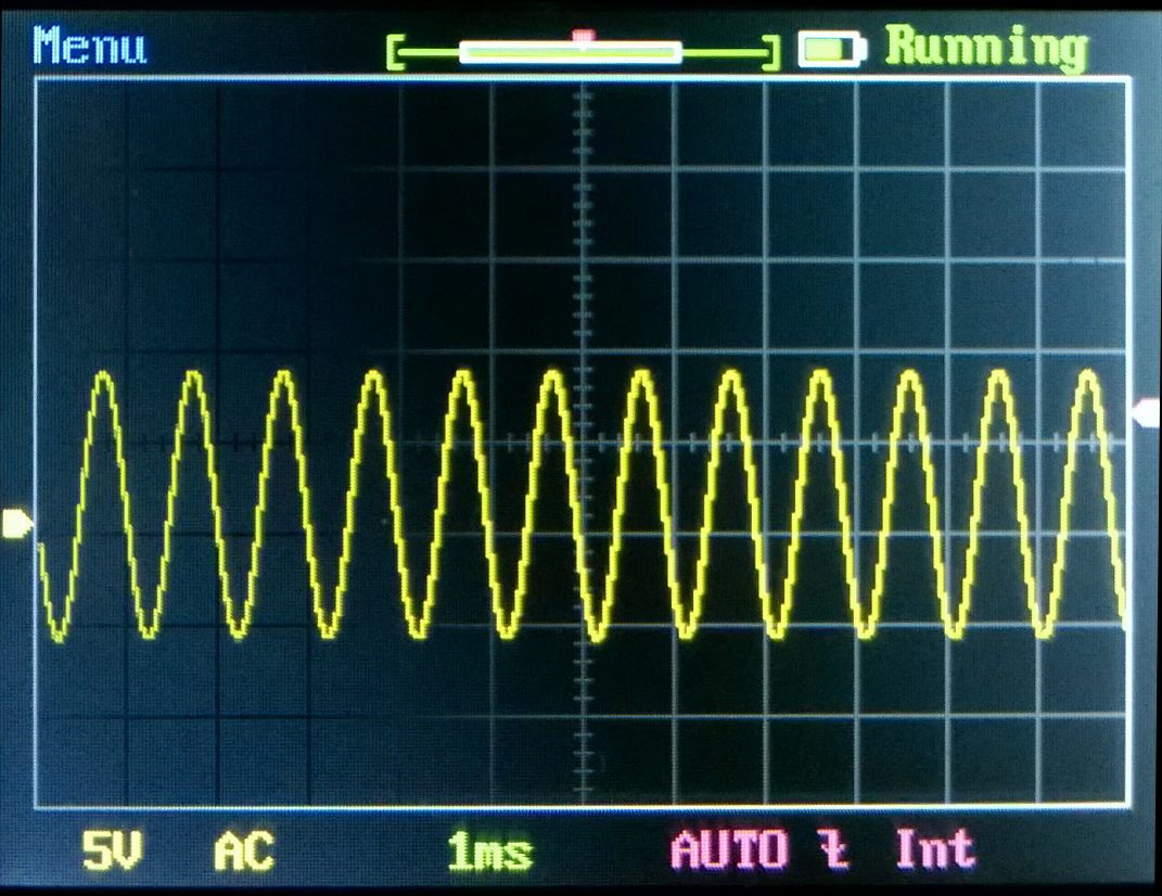
90% of clipping level.Right, that's the negative rail showing something other than a sine-looking wave.
I'll check to see what a lower input level (hence lower output) shows.
What was the output voltage and what was the dummy load?
Load & voltage into it
From my previous post...
"...across an 8-ohm noninductive resistor driven with a 1 kHz sine wave..." [this resistor measured 8.02 ohms]
"...the 'scope shows about 32 volts peak-to-peak, that's 60 watts into 8 ohms...."
This is a sine wave, so RMS = 0.3535* Vp-p, or 11.3 volts RMS in this case. My earlier calculation is incorrect, oops, 11.3 volts is just under 16 watts RMS into an 8 ohm load, NOT 60 watts.
90% of clipping level.
What was the output voltage and what was the dummy load?
From my previous post...
"...across an 8-ohm noninductive resistor driven with a 1 kHz sine wave..." [this resistor measured 8.02 ohms]
"...the 'scope shows about 32 volts peak-to-peak, that's 60 watts into 8 ohms...."
This is a sine wave, so RMS = 0.3535* Vp-p, or 11.3 volts RMS in this case. My earlier calculation is incorrect, oops, 11.3 volts is just under 16 watts RMS into an 8 ohm load, NOT 60 watts.
Power = IV = I^2*R = V^2/R
Power = IacVac = Iac^2*R = Vac^2/R, when sinewave
Power = IpkVpk/2 = Ipk^2*R/2 = Vpk^2/R/2 when sinewave
Thus the formula you need without having to do any conversions is Power = Vpk^2/R/2
and confirms your corrected output power as 16W into 8r0 from 16Vpk and 2Apk
Power = IacVac = Iac^2*R = Vac^2/R, when sinewave
Power = IpkVpk/2 = Ipk^2*R/2 = Vpk^2/R/2 when sinewave
Thus the formula you need without having to do any conversions is Power = Vpk^2/R/2
and confirms your corrected output power as 16W into 8r0 from 16Vpk and 2Apk
Results at lower power level
I reduced the 1 kHz sinewave signal generator output until the current waveform on both rails showed good sine waves on the 'scope.
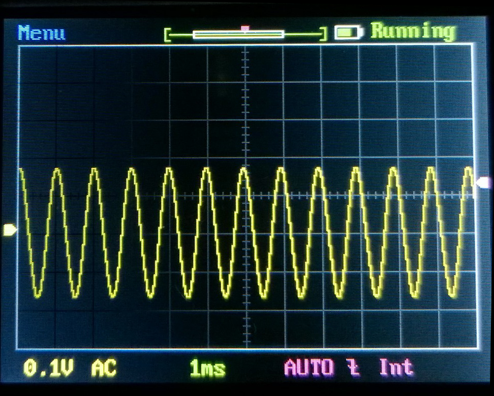
Here's the output of the Aleph-M across the 8 ohm non-inductive resistor load
Nice sine wave, of course, just about exactly 15 V p-p. which is 5.3 V RMS, Ohms law shows that to be about 3.8 watts RMS.
Here is the negative rail current waveform, nice sine here. A little more input signal level causes this to start to distort visually, until at maximum drive it looks like the waveform in the first 'scope photo post.
And here is the positive rail current waveform
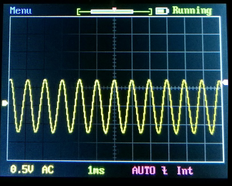
So, at around ~4 watts output this seems to be solidly in class-A and starts moving out of class A when driven to higher power levels.
Regardless, remaining in class A or pushed beyond it, this amplifier, like any other audio amp, needs a power supply that has low sink or source impedance across the audio band- which is the answer to my initial question.
That means, when I am designing the filter / reservoir capacitor bank for the power supply for a pair of these amplifier, I need to pay attention not only to performance at AC ripple frequencies, but also need to select capacitors based on their impedance at frequencies up to 20~50 kHz. This doesn't require any super-exotic capacitors, lots of aluminum electrolytic capacitors from Elna, Panasonic and Nichicon (among others) will work well.
I reduced the 1 kHz sinewave signal generator output until the current waveform on both rails showed good sine waves on the 'scope.
Here's the output of the Aleph-M across the 8 ohm non-inductive resistor load
Nice sine wave, of course, just about exactly 15 V p-p. which is 5.3 V RMS, Ohms law shows that to be about 3.8 watts RMS.
Here is the negative rail current waveform, nice sine here. A little more input signal level causes this to start to distort visually, until at maximum drive it looks like the waveform in the first 'scope photo post.
And here is the positive rail current waveform
So, at around ~4 watts output this seems to be solidly in class-A and starts moving out of class A when driven to higher power levels.
Regardless, remaining in class A or pushed beyond it, this amplifier, like any other audio amp, needs a power supply that has low sink or source impedance across the audio band- which is the answer to my initial question.
That means, when I am designing the filter / reservoir capacitor bank for the power supply for a pair of these amplifier, I need to pay attention not only to performance at AC ripple frequencies, but also need to select capacitors based on their impedance at frequencies up to 20~50 kHz. This doesn't require any super-exotic capacitors, lots of aluminum electrolytic capacitors from Elna, Panasonic and Nichicon (among others) will work well.
Don't do the conversion, just use the appropriate formula. It's quicker and avoids inaccuracies: 15*15/16=3.52W into 8r0I reduced the 1 kHz sinewave signal generator output until the current waveform on both rails showed good sine waves on the 'scope.
Here's the output of the Aleph-M across the 8 ohm non-inductive resistor load.............
Nice sine wave, of course, just about exactly 15 V p-p. which is 5.3 V RMS, Ohms law shows that to be about 3.8 watts RMS.
Yes the last capacitors in the PSU supply the low frequency current demands.Here is the negative rail current waveform, nice sine here. A little more input signal level causes this to start to distort visually, until at maximum drive it looks like the waveform in the first 'scope photo post...............
So, at around ~4 watts output this seems to be solidly in class-A and starts moving out of class A when driven to higher power levels.
Regardless, remaining in class A or pushed beyond it, this amplifier, like any other audio amp, needs a power supply that has low sink or source impedance across the audio band- which is the answer to my initial question.
That means, when I am designing the filter / reservoir capacitor bank for the power supply for a pair of these amplifier, I need to pay attention not only to performance at AC ripple frequencies, but also need to select capacitors based on their impedance at frequencies up to 20~50 kHz. This doesn't require any super-exotic capacitors, lots of aluminum electrolytic capacitors from Elna, Panasonic and Nichicon (among others) will work well.
The MF and HF decoupling, if they are fitted, supply the MF and HF current demands of the amplifier and individual amplifier stages.
When the local supply rail decoupling is omitted, then the inability of the PSU to meet the fast changing current demands can affect the amplifier performance.
Ohm's law is about proportionality between voltage and current, not about calculating power.
Last edited:
Ohm's law is about proportionality between voltage and current, not about calculating power.
Well, Knowing V and R, you can use Ohms Law to calculate I and then knowing I and V you calculate P.... roundabout way, but reaches the answer. An extra step, to be sure- but I remembered Ohms' Law and never memorized the simplified formula you used.
proportionality between voltage and current
Ohm's Law has nothing to do with power.Ohm's Law deals with the relationship between voltage and current in an ideal conductor. This relationship states that: The potential difference (voltage) across an ideal conductor is proportional to the current through it. The constant of proportionality is called the "resistance", R.
Power = E x I, and that is not Ohms law, correct. However, power calculation is so closely bound to the E, I and R of Ohms Law, that they are usually taught as one concept, as in the following textbooks / tutorials
https://www.allaboutcircuits.com/textbook/direct-current/chpt-2/calculating-electric-power/
http://www.electronics-tutorials.ws/dccircuits/dcp_2.html
https://www.allaboutcircuits.com/textbook/direct-current/chpt-2/calculating-electric-power/
http://www.electronics-tutorials.ws/dccircuits/dcp_2.html
So, at around ~4 watts output this seems to be solidly in class-A and starts moving out of class A when driven to higher power levels.
Since you have a healthy bias current, it is possibly too much gain in the
Aleph current source. Try a 2.2 Kohm resistor on the Gate of the PNP
instead of the 1.5K.
Regardless, remaining in class A or pushed beyond it, this amplifier, like any other audio amp, needs a power supply that has low sink or source impedance across the audio band- which is the answer to my initial question.
I don't recall, did we see the rail voltages without the 1 ohm resistors?
Could you offer a simple diagram of your power supply, reservoir and filter caps and where the 1 Ohm, current sensing resistors are placed.
It may help to deduce why the two halves of your supply is modulated unequally. You have to keep in mind that the speaker current flows through the capacitors of your power supply and if the "ripple" caused by the audio signal is not equal on each rail there may be a problem with a capacitor.
In a dual power supply your capacitors has two functions, one is to act as a power reservoir for the amp in the half cycles of the supply and the second is to provide a DC decoupled low impedance path for the audio current through the speakers.
Last edited:
Could you offer a simple diagram of your power supply, reservoir and filter caps and where the 1 Ohm, current sensing resistors are placed.
It may help to deduce why the two halves of your supply is modulated unequally.
Isn't that because it's a single ended amplifier?
I don't recall, did we see the rail voltages without the 1 ohm resistors?
Measured ± 18.0 V dc for the rails at the board, after the 1 ohm resistors
Could you offer a simple diagram of your power supply, reservoir and filter caps and where the 1 Ohm, current sensing resistors are placed.
It may help to deduce why the two halves of your supply is modulated unequally. You have to keep in mind that the speaker current flows through the capacitors of your power supply and if the "ripple" caused by the audio signal is not equal on each rail there may be a problem with a capacitor.
In a dual power supply your capacitors has two functions, one is to act as a power reservoir for the amp in the half cycles of the supply and the second is to provide a DC decoupled low impedance path for the audio current through the speakers.
For testing I am using a lab power supply, constant voltage regulated supply 10 amp capacity on both negative and positive rails, ± 0.1 mV regulation
THANKS
I will try that, many thanks.
I'll post how this changes operation in terms of power output produced when the negative rail current waveform starts to change away from a nice sine wave as input level increases.
Since you have a healthy bias current, it is possibly too much gain in the
Aleph current source. Try a 2.2 Kohm resistor on the Gate of the PNP
instead of the 1.5K.
I will try that, many thanks.
I'll post how this changes operation in terms of power output produced when the negative rail current waveform starts to change away from a nice sine wave as input level increases.
The thing is, your waveform looks like crossover distortion which
occurs when the positive current source goes into cutoff.
occurs when the positive current source goes into cutoff.
For testing I am using a lab power supply, constant voltage regulated supply 10 amp capacity on both negative and positive rails, ± 0.1 mV regulation
Are you current limiting the supply. I ask because you cannot apply any current limiting unless it is at least twice the CCS current. What Nelson says is right, it looks like the CCS is falling over, but I suspect it is the current limiting that you may have set in the power supply that is causing the problem.
Turn any current limit off or set it full 10 amps and test again.
The thing is, your waveform looks like crossover distortion which
occurs when the positive current source goes into cutoff.
Single Ended runs perfectly until it falls over when the CCS runs out of steam and then distorts terribly, there is hardly a smooth transition.
Last edited:
What one must keep in mind is that when the active tranny conducts a lot then the positive supply needs to come forth with the current flowing through the speaker, and that of the CCS, thus twice the bias current.
If your supply current is of limited capability, then this becomes the bottleneck and you would see this on the one power rail only.
Class A SE nuts, like myself use hugely over designed power supplies simply because of issues such as these, that is why you end up with many Farad caps to supply any instantaneous current......
Are you current limiting the supply. I ask because you cannot apply any current limiting unless it is at least twice the CCS current. What Nelson says is right, it looks like the CCS is falling over, but I suspect it is the current limiting that you may have set in the power supply that is causing the problem.
Turn any current limit off or set it full 10 amps and test again.
Current limiting is turned off. Power supply is in constant voltage mode, not constant current mode. 10 amps available from both positive and negative rails. Power supply meters show about 2.2 amps current on each rail when amplifier is at idle.
- Status
- Not open for further replies.
- Home
- Amplifiers
- Pass Labs
- Power supply impedance and class A amplifiers?