Ok. I think that you need 5 minutes to measure what I suggested in post #72. Measure amplitudes of ac voltages across each 0.33 resistor. They should be the same if aleph ccs is configured for max. efficiency. If not, you should tweek the value of that lower 1k5 resistor to make the amplitudes the same. When doing this, connect load resistor to the output, and for start check it with lower input voltage.
If class A output stage is not push-pull, let X = output stage bias current (in amps)
If class A output stage is push-pull, let X = 2 * output stage bias current (in amps)
Then I would be happy, personally, if my power supply's output impedance remained below Z ohms, for all frequencies from 10 Hz to 100 kHz. The number Z is calculated thus:Example 1: A class-A amplifier with a constant current source pullup in its output stage, runs at 3.5 amperes of bias. Then Z = 0.5 / 3.5 = 0.14 ohms
Example 2: A class-A amplifier with a push pull output stage, runs at 2.0 amperes of bias. Then Z = 0.5 / 4 = 0.12 ohms.
But of course, my preferences and "happiness threshold" might be different from yours.
If class A output stage is push-pull, let X = 2 * output stage bias current (in amps)
Then I would be happy, personally, if my power supply's output impedance remained below Z ohms, for all frequencies from 10 Hz to 100 kHz. The number Z is calculated thus:
- Z = 0.5 / X
Example 2: A class-A amplifier with a push pull output stage, runs at 2.0 amperes of bias. Then Z = 0.5 / 4 = 0.12 ohms.
But of course, my preferences and "happiness threshold" might be different from yours.
Setting actual resistance aside, that would imply about 150,000 uF.
Not an unreasonable value for happiness.
Not an unreasonable value for happiness.
I was thinking the OP might decide to build voltage regulators a la the Levinson ML-2, in which case 10 milliohms at 10 Hz is eminently doable.
Regulated supply options
A pair of σ22 supplies would probably work well The σ22 regulated power supply
A pair of σ22 supplies would probably work well The σ22 regulated power supply
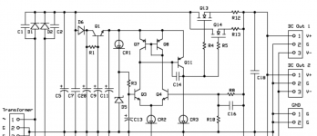
I'm not a big fan of un-degenerated current mirrors, as used in the sigma22 regulated power supply. (example: Q7-Q8). Mismatched VBEs can twist an un-degenerated mirror quite badly.
_
I don't understand what you mean by "twist?" Poor regulation? Noise? High sink / source impedance?
While a lot of this discussion has been over my head, I have really learned a lot here about power supplies and also about this amplifier topology. A lot of it I still don't have a full grasp of, but I'm learning..... getting closer to some understanding of the electronics involved.
"un-degenerated current mirror" now that's one I had to look up, and that alone would take me a long time to comprehend.... but I took away that an un-degenerate current mirror assumes something like perfect, matched performance of the parts so that "both sides of the mirror" are behaving as theory says they should.... and I think Mark Johnson's point is that such a design might be good in THEORY but with real world parts, not so much. And further that the Sigma 22 uses such a design. I THINK that's his point....
Corollary to this.... a current mirror in which such close component matches are not part of the design assumptions must have some mechanism(s) in the design to compensate for these variances in parts ... would it be proper to call such a design a "degenerate" current mirror?
Resistors connected in series with the emitter leg are called "degeneration resistors", see Bob Cordell's power amplifier design book Fig 2.5b and/or section 3.2. In a current mirror, degeneration resistors ameliorate the errors ("twist") caused by mismatched transistors. Try it in circuit simulation such as LTSPICE.
But what's important here is that a multi-ampere voltage regulator with reasonable amounts of gain and reasonable amounts of negative feedback, is likely to provide an extremely low output impedance when powering a class-A amplifier. Much lower than the impedance guideline suggested in post #82 above. Just avoid obvious circuit design errors like un-degenerated current mirrors.
But what's important here is that a multi-ampere voltage regulator with reasonable amounts of gain and reasonable amounts of negative feedback, is likely to provide an extremely low output impedance when powering a class-A amplifier. Much lower than the impedance guideline suggested in post #82 above. Just avoid obvious circuit design errors like un-degenerated current mirrors.
- Status
- Not open for further replies.
- Home
- Amplifiers
- Pass Labs
- Power supply impedance and class A amplifiers?