Wouldn't a class-A push-pull balanced amplifier normally be operated within the class A regime? I mean, what would be the purpose of building such a thing, if not to use it in class A? If the amplifier is expected to be pushed into class B, how is it a class A amplifier?
The answer lies in the observation that the amp's designer has no power over the choice of load impedance by the user. A push-pull classA will move from classA to AB if the load impedance is lower than that designed for.
Are you saying that it's impossible to make a class A push pull design that remains in class A?
This gets an affirmative answer if the load impedance can be anything the end-user chooses.
OK, so let's consider the other case - Single-ended class A amplifiers biased by constant current sources. Pass says "Amplifiers biased by constant current sources will have
constant draw (obviously)" - and, please I am not truncating the sentence to mislead anyone, I am just trying now to understand a single-ended amp of this type, and so now I am not asking about, or referring to, a balanced push-pull design.
Nelson's incorrect if he means that any classA amp containing current sources (presumably meaning for output stage loading/bias) is going to draw a static current from the supply.
A "classic" single ended amplifier operating in ClassA is simple. It cannot sink more current than what it is biased at. The CCS (or resistor) sets a current sinking limit.
It can supply more current than the bias, but that would rely on an unsymetrical waveform to take advantage of that ability.
This version draws a varying current from the supply as shown in post8.
Push-Pull does not have that hard limit. If one sets the bias to a particular value then the ClassA limit is approximately double the bias current value. Although there are claims that some forms of this topology can supply/sink more than double the bias current.
But the BIG advantage of Push-Pull is that they can transition from ClassA to ClassAB if the current demand exceeds double the ClassA bias.
Most speakers can demand much more current than their equivalent resistance.
at least 150% is expected from a full range driver without any crossover.
exceeding 300% has been proven for both moderate and severe reactance crossovered speakers.
These exceptional current demands coincide with fast transients. They are short term.
As such they do not usually blow up amplifiers, there is not enough heating effect in the short term transients. They can easily demand more than the ClassA limit.
Last edited:
As this thread shows, the term "Class A" does not contain enough information to answer questions like "is the current draw constant?". The question can only be answered for particular Class A topologies under particular signal and load conditions.
A related question is "is the average current draw constant?" People often get this and the first question mixed up, and also fail to state over what time period the average is being taken. For some Class A circuits used below clipping the average current draw may be constant (unlike Class B) even when the current draw is not. This could mean that the subsonic source impedance of the supply is less important than for Class B.
A related question is "is the average current draw constant?" People often get this and the first question mixed up, and also fail to state over what time period the average is being taken. For some Class A circuits used below clipping the average current draw may be constant (unlike Class B) even when the current draw is not. This could mean that the subsonic source impedance of the supply is less important than for Class B.
only from the rail the ccs is on
the other rail has varying current from the SE output device
I was referring to a ccs biasing a Common Source single-ended circuit,
sorry about the confusion.
Last edited:
trying to think about power supply design in terms of it's impedance at audio frequencies.
There are a lot of things, which takes attention there.
1. Active or passive supply regulation.
2. Shunt or series supply voltage regulation topology.
3. Feedback depth and stability inside the supply regulation loop.
4. ESR of the last capacitors and parasitic inductance of leading wires.
5. Trafo or SMPS design.
Now, let's answer to main question - how much Joules of energy you want to store per Watt of output power.
Active regulator only maintain supply voltage (impedance, keeping in mind load current) and provide unrippled rails, they can't store energy.
Let's assume, we need some mOhms in audioband (and up to ones-tens of MHz) for small-signal circuitry (consuming up to dozens of mAmps) and tens-dozen of mOhms for high-current output stages.
Let's suppose some Member gives you a value................Now, let's answer to main question - how much Joules of energy you want to store per Watt of output power.............
How will you use it?
I'll guess at 1012Joules.
What does that tell you? What will you do with it?
What if my guessed at value is completely wrong by one, or two decades?
What will that do to your ClassA amplifier?
Let's suppose some Member gives you a value.
How will you use it?
I will simply calculate needed capacitors value based on rails voltage.
And then, of course, i will tell the price.
I'll guess at 1012Joules. What does that tell you?
😉
This will tell me you are joking.
Or you have huge disposable income.
Or you aren't think before answering.
Or you be the first in taking psychologist's gown.
Or i must answer that atomic plant are better.
Many variants, you even can suggest yours.
What will you do with it?
Completely nothing. This will be your amps energy reservoir, not mine.
What if my guessed at value is completely wrong by one, or two decades?
This will straightly affect your amp's sounding. Just try 220 uF, 2.200 uF and 22.000 uF.
What will that do to your ClassA amplifier?
Mine have an order of ones J/Wt.
That was not the OP's question. However, the answer to this different question which you have asked depends on mains frequency and amplifier PSRR. Making typical assumptions lead to roughly 1J of energy storage for each watt of output, but a factor of 10 either way is possible.BesPav said:Now, let's answer to main question - how much Joules of energy you want to store per Watt of output power.
Fortunately active regulators are not required to store energy. That is the job of reservoir capacitors - the clue is in the word 'reservoir'.Active regulator only maintain supply voltage (impedance, keeping in mind load current) and provide unrippled rails, they can't store energy.
For small signal circuitry consuming only mA maybe low ohms are adequate, with a bandwidth from around DC up to a bit above the audio band. MHz not likely to be needed, but mHz may be important.Let's assume, we need some mOhms in audioband (and up to ones-tens of MHz) for small-signal circuitry (consuming up to dozens of mAmps) and tens-dozen of mOhms for high-current output stages.
only from the rail the ccs is on
Not only, bridged A-class OPS will consume constant current too.
That was not the OP's question.
Of course! You are clearly right!
Let's rephrase TS question - do we need regulated supply for the OPS?
That is not a rephrase of the question. The question was about impedance. Questions about regulated supplies relate to methods of achieving whatever impedance answers the original question. His question was about requirements; your new question is about implementation.BesPav said:Let's rephrase TS question - do we need regulated supply for the OPS?
His question was about requirements
That question can't be answered standalone. Or answer will be simply and stupid - as low as possible with active or capacitive character at least to amplifier's upper gain margin frequency.
Digging inside we opens a lot of tied parameters - open-loop gain, power supply rejection ratio, input-related noise, noise spectral density, power demands, and etc.
It's pointlessly to design best possible powersupply without knowledge about power consumer.
"As low as possible" would be a simple and stupid answer. That does not mean that the question is faulty. Questions about requirements have to be answered before ways of meeting those requirements can be considered. He did not ask about "best possible powersupply". Why not give us your answer to his question, instead of inventing different questions?
This might be a useful suggestion from Rod Elliott for the OP since the design he is referring to uses a negative supply rail. The '"small" detail' is the varying negative rail current.
This "small" detail seems to have received scant reference in any of the articles I have read, but it will make a very big difference to the power supply. In this respect, I do not feel that the single ended version should be operated from a dual supply. If it is so important to you to eliminate the coupling capacitor, then I suggest that either a push-pull Class-A design be used, or build separate power supplies for each polarity.
Why not give us your answer to his question
Ok, i'm using regulator with output impedance (calculated as V/I) shown as green line compared with standalone LM317 as blue line.

OK here is my answer
The simple answer to my original question is that, YES, the power supply for a mini-Aleph class A amplifier DOES need to sink / source audio-frquency currents.
Here's the output of a mini-Aleph with ± 18 volt rails, across an 8-ohm noninductive resistor driven with a 1 kHz sine wave
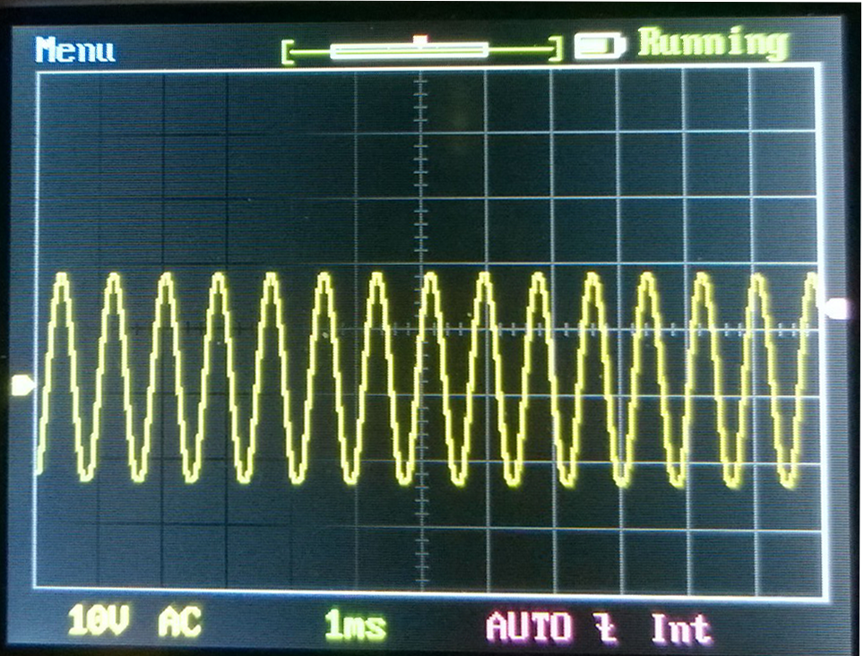
Nice output there. Fair amount of power. (Am I driving the amplifier past Class A here? I thought the mini-Aleph was a 10-watt amplifier, the 'scope shows about 32 volts peak-to-peak, that's 60 watts into 8 ohms.....?)
I have 1 ohm resistors in series with each rail for current sensing, and I've adjusted the supply voltage so that the amplifier itself gets ± 18 volts.
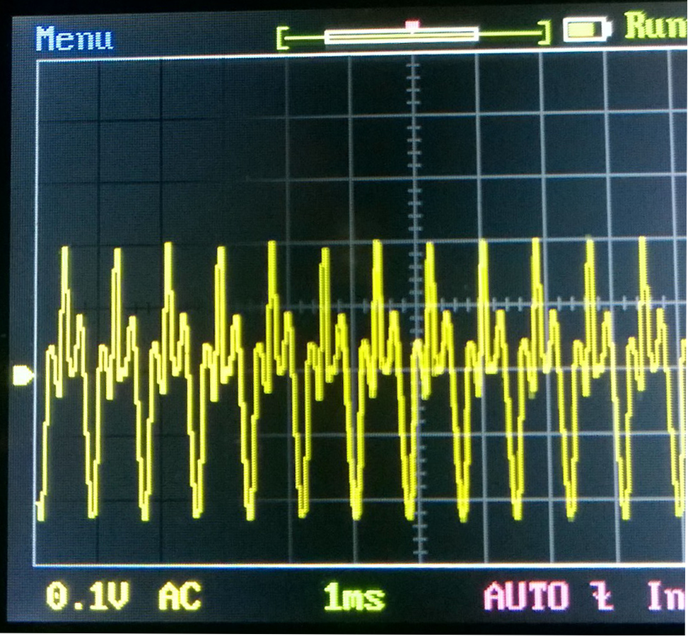
Here's the voltage drop across the negative rail current sensing resistor
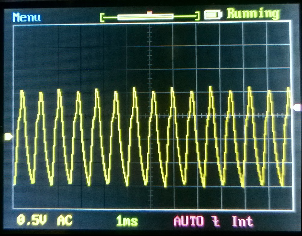
And here's the voltage drop across the positive rail current sensing resistor
The negative rail shows a waveform which is ~0.42 p-p, and using Ohms law, this is a 420 mA current swing at 1 kHz.
The positive rail shows a greater swing, 2 volts peak-to-peak, that's a 2- amp current swing.
So- unless I'm actually driving this amplifier out of class A and into class B - the answer to my question is that a class A amp has pretty much the same power supply sink and source impedance requirements you'd want for a class AB amp; like someone said, "as low as possible."
I just couldn't get the "feel" of the current flow from looking at the schematic. I didn't so an analysis -I'm too lazy to do the math to chase currents through the schematic - but now I have the answer I sought, from a practical standpoint.
Thanks for everyone who contributed. 🙂
The simple answer to my original question is that, YES, the power supply for a mini-Aleph class A amplifier DOES need to sink / source audio-frquency currents.
Here's the output of a mini-Aleph with ± 18 volt rails, across an 8-ohm noninductive resistor driven with a 1 kHz sine wave
Nice output there. Fair amount of power. (Am I driving the amplifier past Class A here? I thought the mini-Aleph was a 10-watt amplifier, the 'scope shows about 32 volts peak-to-peak, that's 60 watts into 8 ohms.....?)
I have 1 ohm resistors in series with each rail for current sensing, and I've adjusted the supply voltage so that the amplifier itself gets ± 18 volts.
Here's the voltage drop across the negative rail current sensing resistor
And here's the voltage drop across the positive rail current sensing resistor
The negative rail shows a waveform which is ~0.42 p-p, and using Ohms law, this is a 420 mA current swing at 1 kHz.
The positive rail shows a greater swing, 2 volts peak-to-peak, that's a 2- amp current swing.
So- unless I'm actually driving this amplifier out of class A and into class B - the answer to my question is that a class A amp has pretty much the same power supply sink and source impedance requirements you'd want for a class AB amp; like someone said, "as low as possible."
I just couldn't get the "feel" of the current flow from looking at the schematic. I didn't so an analysis -I'm too lazy to do the math to chase currents through the schematic - but now I have the answer I sought, from a practical standpoint.
Thanks for everyone who contributed. 🙂
For a Push-Pull ClassA amplifier running on Dual polarity supplies and below it's ClassA current limit, the output current is equal to the DIFFERENCE in supply rail currents.
When the amplifier is at quiescent state (no output current other than Hum+Noise) the difference in supply rail currents will be virtually zero.
During this test the current into/out of the zero volts supply rail is virtually zero.
When the output current has increased to some value at an instant in time, say X Amperes, the DIFFERENCE in supply rail currents will be X Amperes, i.e one rail will have gone down by X/2 Amperes and the other rail will have gone up by X/2 Amperes.
Looks like you have left Class A on that waveform.
Which waveform? The output, negative rail current or positive rail current?
Further info:
Amplifier draws ~2.2 amps per rail at idle, @ ± 18.0 vdc
Input signal is single-ended 1.2 volts RMS @ 1 kHz sine wave (drives amplifier to about 90% of clipping)
Amplifier schematic (as found on the Internet someplace...)
An externally hosted image should be here but it was not working when we last tested it.
Current through both rails should show a sine wave, perhaps with some
measure of distortion, but one of your waveforms does not.
measure of distortion, but one of your waveforms does not.
Current through both rails should show a sine wave, perhaps with some
measure of distortion, but one of your waveforms does not.
Right, that's the negative rail showing something other than a sine-looking wave.
I'll check to see what a lower input level (hence lower output) shows.
- Status
- Not open for further replies.
- Home
- Amplifiers
- Pass Labs
- Power supply impedance and class A amplifiers?