Member
Joined 2009
Paid Member
toffee nose ! ha
Well I'd be very happy with one of those but I don't think 21 step is enough - I have a Noble pot which has indents and I always wanted to set it somewhere between indents so I replaced it with a smooth Alps.
On the other hand, these eBay things are so cheap it wouldn't do harm to try one.
Well I'd be very happy with one of those but I don't think 21 step is enough - I have a Noble pot which has indents and I always wanted to set it somewhere between indents so I replaced it with a smooth Alps.
On the other hand, these eBay things are so cheap it wouldn't do harm to try one.
Member
Joined 2009
Paid Member
Relays
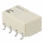
I was all set on solid-state relays (idea from the Clone Note) but look how cute these little Omron relays are. I get a DPDT relay, latching or non-latching with 'Ag (Au-Alloy contact)' contacts. There may be some benefits from having a NC switch in the circuit for example.
I was all set on solid-state relays (idea from the Clone Note) but look how cute these little Omron relays are. I get a DPDT relay, latching or non-latching with 'Ag (Au-Alloy contact)' contacts. There may be some benefits from having a NC switch in the circuit for example.
Attachments
I was all set on solid-state relays (idea from the Clone Note) but look how cute these little Omron relays are. I get a DPDT relay, latching or non-latching with 'Ag (Au-Alloy contact)' contacts. There may be some benefits from having a NC switch in the circuit for example.
Shorting non-selected inputs - less cross-talk.
Question - have you simulated your circuits on square wave inputs with suitable loads with your shunt regulators to check the integrity of the supply rails?
I am mindful that currents can flow in opposite phase simultaneously in such as within a simple two stage circuit. Looking at that Krell pre-amp and all the decoupling capacitors look over the top - but is it?
Just wondering if they are regulating individual stages in a circuit and decoupling these separately.
Member
Joined 2009
Paid Member
I did - nothing really bad happened.
I've uploaded my file - maybe you can check too ?
I have looked - All good as is - I had a passing thought about compound in lieu of the Darlingtons but no in that regard.
Member
Joined 2009
Paid Member
I have looked - All good as is
Attachments

Member
Joined 2009
Paid Member
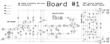
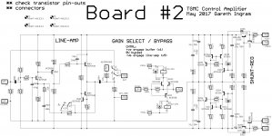
I've updated the schematic in my layout software.
In the end, I didn't adopt the PSRR improvement change to the phono - I don't want to deviate too much from the original and with the shunt regulator on-board I'm not concerned about the low native PSRR.
The gain stage is taken from the Naim. But the original devices are unobtainable. I've noticed some published clones have added a stabilizing capacitor base-collector on the output device for use with modern transistors. I've included the option - hopefully not required.
Attachments
Member
Joined 2009
Paid Member
Member
Joined 2009
Paid Member
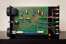
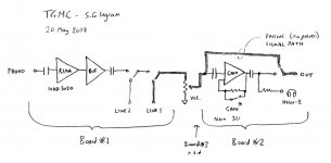
Here's how it is supposed to fit together.
Is there any chance the NAD style phono could drive a 20 K pot to 2 Vrms? I haven't done the sums so only guessing it could. If the buffer is required could it be converted to 3180+318 uS active and 75 uS passive? Naturally listen to both.
You will need to improve that regulator.In the end, I didn't adopt the PSRR improvement change to the phono - I don't want to deviate too much from the original and with the shunt regulator on-board I'm not concerned about the low native PSRR.
Try to use as close parts as you can to the original.The gain stage is taken from the Naim. But the original devices are unobtainable. I've noticed some published clones have added a stabilizing capacitor base-collector on the output device for use with modern transistors. I've included the option - hopefully not required.
Sure.Is there any chance the NAD style phono could drive a 20 K pot to 2 Vrms?
Member
Joined 2009
Paid Member
We've been around that block already, we have 3 options when we build it, one replaces the current mirror with a resistor, one uses Darlington shunt devices instead of not, and the other options is a combination of both. All these options results in different Zout. All options appear to be stable. I favour the low Zout so it's good to have that options. What other options would you add ?You will need to improve that regulator.
I've looked on the 'net and recommendation is to use BC550/60 parts as replacements. Partly, that's on account of compatible pin-out with the e-line devices. With the power amp VAS we wanted to retain the Cob and luckily these parts are still available. For the pre-amp, what are the distinguishing features of the original parts that I should seek out ??Try to use as close parts as you can to the original.
I'm sure it could drive it without and we have the option not to install the buffer components on the pcb at all. The buffer simulates with negligible distortion and has gobs of headroom; it's open loop and has no obvious stability risk. But my simulations say that there will be increasing fall-off at low frequencies, and associated phase shifts, without the buffer.Is there any chance the NAD style phono could drive a 20 K pot to 2 Vrms?
Back in post#16 the first item on my list of goals was to be able to use this box in passive-mode. This is to allow me to have just a pure volume control between source and power amplifier. It will allow me to use the box when an external power connection for the preamp is unavailable and I will also be able to listen directly to the difference between active vs passive. From what I have read, this means using a volume pot of lower impedance than 20k ohm. Something in the range 1k to 5k would be better. I don't plan to have a weak source component for driving said potentiometer, namely i) I have a phono source with a buffer, ii) I have an FM tuner into which I've already built a single-ended output buffer (for use with headphones) that can drive a small heard of buffalo, iii) my digital source is going to be another project (!!) where I too can control the output impedance as I see fit.
This sounds like a really interesting idea - what does that look like and what are the benefits ?If the buffer is required could it be converted to 3180+318 uS active and 75 uS passive? Naturally listen to both.
Last edited:
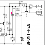
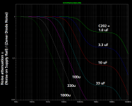
You might want to call a meeting with your circuit theory consultants, and jointly dream up a way to model and simulate the beneficial effects of "noise filtering capacitor" C202. Since it is connected in parallel with Zener diode Z201, you might imagine that there is a struggle for dominance, and the winner is the component whose impedance (at a given frequency) is lowest. But don't let me, or the textbooks, prejudice your analysis. Come at it from a fresh perspective and see what pops out.
Maybe, just maybe, you might get results similar to those attached below. (Or maybe you'll conclude I am spectacularly wrong -- who knows?). When you've got your plot you can then ask yourself the questions
Then either choose a new value of C202 based on the answers, or redesign the circuit, or both ... ?
_
Maybe, just maybe, you might get results similar to those attached below. (Or maybe you'll conclude I am spectacularly wrong -- who knows?). When you've got your plot you can then ask yourself the questions
- How much attenuation of zener diode noise do I want, at 20 kHz?
- How much attenuation of zener diode noise do I want, at 1 kHz?
_
Attachments
Member
Joined 2009
Paid Member
We are the circuit consultants !
I remember there was quite a bit of chat on the Salas thread about this. In the end, he said that listening tests showed the Zener was not the limiting factor (vinyl surface noise was very dominant). But he uses larger caps across the zener than I've indicated there. Even a quick look on Digikey shows that I can go with a 330uF in this position, same size footprint, 50V rating.
I remember there was quite a bit of chat on the Salas thread about this. In the end, he said that listening tests showed the Zener was not the limiting factor (vinyl surface noise was very dominant). But he uses larger caps across the zener than I've indicated there. Even a quick look on Digikey shows that I can go with a 330uF in this position, same size footprint, 50V rating.
Member
Joined 2009
Paid Member
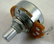
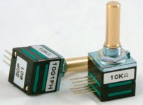
I popped into the PartsConnexion webstore to look at volume pots. Here's a couple of options for smoothly variable potentiometers and a couple of options for stepped attenuators.
Pots:
a) Alpha 10k ohm LINEAR. Cheap as chips. Would buy several, check for matching at low level, add law-faked resistor.
b) TDK 10k ohm LOG. About $40 so better be well-matched out of the gate and apparently they have that reputation.
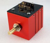
c) Khozmo 10k ohm shunt-style is apparently a make-before-break (I had wrong info before) and offers 48 steps so this should work nice. About $180.
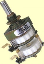
d) DACT 10k ohm, only 23 steps which is not attractive to me. About $220.
Pots:
a) Alpha 10k ohm LINEAR. Cheap as chips. Would buy several, check for matching at low level, add law-faked resistor.
b) TDK 10k ohm LOG. About $40 so better be well-matched out of the gate and apparently they have that reputation.
c) Khozmo 10k ohm shunt-style is apparently a make-before-break (I had wrong info before) and offers 48 steps so this should work nice. About $180.
d) DACT 10k ohm, only 23 steps which is not attractive to me. About $220.
Attachments
I would expect to see some decent caps placed across the zener diodes to shunt as much of their noise away as possible
330uF across the zener diodes reduces zener noise by a factor of 3 at 1 kHz. Whoop de doo.
I am confident that yourself, nigel pearson, traderbam, mjona, and Nico Ras can dream up a modifcation of the circuit (adding 2 or fewer new components), in which the modified version reduces zener noise by a factor of 1000 at 1 kHz. Then you can decide whether the benefit justifies the cost of the modification.
Hi Mark, sorry to advise I am no circuit designer and have no idea what you are talking about so I will just take your word for it.
Personally I do not like anything that shunts anything around - to me that is plain bullying.
Member
Joined 2009
Paid Member
you build without any kind of capacitors ?Personally I do not like anything that shunts anything around - to me that is plain bullying.
hmmm, factor of 1,000. That's not going to happen the brute force way with ever bigger capacitors. So Mark has a different trick in mind. There are i.c. options, but that's the easy way out perhaps. The TL-431 is an op-amp afterall and people have used them to amplify audio I believe ! Perhaps Mark is thinking of a simple filter between zener reference and base input of the first transistor ?
Last edited:
- Status
- Not open for further replies.
- Home
- Source & Line
- Analog Line Level
- TGMC - a modular control pre-amplifier