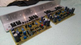
A38 (A40 with two pairs of output transistors in the output) in progress :
Very nice..
Hi sir Mile What transistor can use replacement for bf245? Something simple and easy to obtain. For bf245 need to goo 45km with car and the price is 2.50 euro for 1 bf245. Is too much!!
Thank You!
Thank You!
An externally hosted image should be here but it was not working when we last tested it.
Hi sir Mile What transistor can use replacement for bf245? Something simple and easy to obtain. For bf245 need to goo 45km with car and the price is 2.50 euro for 1 bf245. Is too much!!
Thank You!
An externally hosted image should be here but it was not working when we last tested it.
Replace BF245 with 2k2 resistor.
Regards
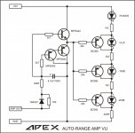
Autorange VU
Sorry to jump in but I think this circuit was posted in this thread a while ago. Schema attached. Can't seem to make it work right. I've built it twice thinking the first time was my bad but the second one came out really good. Anyway, all the led's flash together, in time with the music.I know I'm only using the +HV side and not the -HV side but I'm not looking for accuracy, just some moving lights and a power light to dress up a small solid state power amp I'm building. My +HV is around 25vdc. It's all hooked up to the left side of the amp. Any ideas?
Sorry to jump in but I think this circuit was posted in this thread a while ago. Schema attached. Can't seem to make it work right. I've built it twice thinking the first time was my bad but the second one came out really good. Anyway, all the led's flash together, in time with the music.I know I'm only using the +HV side and not the -HV side but I'm not looking for accuracy, just some moving lights and a power light to dress up a small solid state power amp I'm building. My +HV is around 25vdc. It's all hooked up to the left side of the amp. Any ideas?
Attachments
Hi everyone !
I need reference post for final version of FX14 !! with PCB if possible !
Thank you all
I need reference post for final version of FX14 !! with PCB if possible !
Thank you all
Sorry to jump in but I think this circuit was posted in this thread a while ago. Schema attached. Can't seem to make it work right. I've built it twice thinking the first time was my bad but the second one came out really good. Anyway, all the led's flash together, in time with the music.I know I'm only using the +HV side and not the -HV side but I'm not looking for accuracy, just some moving lights and a power light to dress up a small solid state power amp I'm building. My +HV is around 25vdc. It's all hooked up to the left side of the amp. Any ideas?
So I hooked it up to my bench supply and all the led's light at one time, except for the clip led. I know I should let it go as not working but it will really make my new amp project look good.Any ideas?
So I hooked it up to my bench supply and all the led's light at one time, except for the clip led. I know I should let it go as not working but it will really make my new amp project look good.Any ideas?
AMP OUT on VU connect to GND for test
https://www.youtube.com/watch?v=vBokXBBqbH4
AMP OUT on VU connect to GND for test
https://www.youtube.com/watch?v=vBokXBBqbH4
Same thing. All led's, (except clip), light up at the same time as I slowly bring up bench supply with amp out on vu connected to ground. I didn't use one of the pcb's posted but a small proto board. I've double and triple checked all connections.
Last edited:

That looks like fun but I just don't need that many led's. I bought a case that had a front panel with four led's already in it, for power, data, link and message, but I thought it would look cool if they were VU type meters instead. I just can't seem to make the Apex VU work though.
Sorry to jump in but I think this circuit was posted in this thread a while ago. Schema attached. Can't seem to make it work right. I've built it twice thinking the first time was my bad but the second one came out really good. Anyway, all the led's flash together, in time with the music.I know I'm only using the +HV side and not the -HV side but I'm not looking for accuracy, just some moving lights and a power light to dress up a small solid state power amp I'm building. My +HV is around 25vdc. It's all hooked up to the left side of the amp. Any ideas?
Maybe you can try this, with + HV 25Vdc, it works great from Multisim 14.0 simulation.

Well I made the resistor changes and now all the led's, minus the clip, light up, with no blinking as volume comes up. From that I can see that I just need to get the resistor values right. Or mine just doesn't work. Thanks Kuntarman for the suggestion.
Well I made the resistor changes and now all the led's, minus the clip, light up, with no blinking as volume comes up. From that I can see that I just need to get the resistor values right. Or mine just doesn't work. Thanks Kuntarman for the suggestion.
No need to change anything, you made some mistake.
https://www.youtube.com/watch?v=SuypbC5Ib8Q&t=74s
No need to change anything, you made some mistake.
https://www.youtube.com/watch?v=SuypbC5Ib8Q&t=74s
This is a functional circuit.
I have built one on mine pcb and works fine!
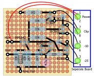
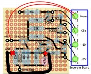
Could it be because I didn't use a pcb design? I just used a small proto board layout, attached. I just can't find the problem.

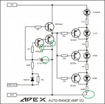
Found, Mistake GND connection.
Sent from my Redmi Note 3 using Tapatalk
But to me, it looks like the ground connects to four things, the 220R resistor, the minus of the 4.7uF cap and the two MPSA92 collectors. If I cut at those two x's, won't it leave the cap and collectors un-grounded?
Attachments
- Home
- Amplifiers
- Solid State
- 100W Ultimate Fidelity Amplifier