Nothing really much you can do now, there's full bunch of SMD parts on bottom of PCB. TP1-TP2 mV adjustment should be trivial, can not imagine how a spark came into equation. Was multimeter set to A instead mV?
I consider myself experienced in this regard but I always approach to setup adjustments with max caution.
Did you like the sound in that 20 hours session or it was just powered without the signal?
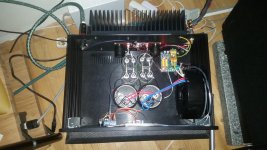
Multimeter was set to voltage I am very sure. R 35 10 ohm and T 16 is blown. Can I buy thoose from you? Or is it better to send it back for repair?
No problem 😉Multimeter was set to voltage I am very sure. R 35 10 ohm and T 16 is blown. Can I buy thoose from you? Or is it better to send it back for repair?
All First One v1.4 M modules equipped with brand new instructions. 😉
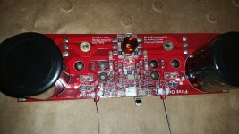
Instructions for L modul please. My L modul is hot with only 60 mv TP 3 -TP 4. Current for the Amp is 1 A ( 230) V ???
Temperatur with big heatsink is 45 C. Do not feel very secure.
45 deg has always been the temp chosen by LC to stabilize, and to provide Warm sound 🙂
Works perfect now 200 Mv. 2x85 Vdc Supply 1 mv dc and 36 Celsius
[/ATTACH]
3,9 kohm resistors to measure at the open end for improved security. I solder the leads for the multimeter to the end. Hope Lazy Cat will forgive me.
Attachments
Last edited:

3,9 kohm resistors to measure at the open end for improved security. I solder the leads for the multimeter to the end. Hope Lazy Cat will forgive me.
Not fully completed
3,9 kohm resistors to measure at the open end for improved security. I solder the leads for the multimeter to the end. Hope Lazy Cat will forgive me.
Safety First One hehe

I would like to connect Power supply to enclosure. Any advice on that? In Denmark it is not Main Earth in all houses.
I can measure some hum at output.
I can measure some hum at output.
Mr. Pass uses and recommends a NTC (CL60?) thermistor from ground to chassis.
These thermistors are very good weapons. I use them also in series with the AC to SMPS when increasing capacitance...
But if you don't have Mains protective Earth...you better instal a good one beforehand.
Cheers,
M.
These thermistors are very good weapons. I use them also in series with the AC to SMPS when increasing capacitance...
But if you don't have Mains protective Earth...you better instal a good one beforehand.
Cheers,
M.
Last edited:
LC, could you please give sim model of your SSA amplifier for troubleshooting purpose?
Many thanks in advance!
Many thanks in advance!
First One Mosfet L is so much better than any other amplifier I have tried. Special in Treble midrange.

First One Mosfet L is so much better than any other amplifier I have tried. Special in Treble midrange.
Great news, but could you elaborate a bit more and tell us your findings regarding the treble and midrange?
Also interested in how the L compares to the M modules
Many thanks!
Claude
L is a grown up amp compared to the M. I got large Duelund speakers.Great news, but could you elaborate a bit more and tell us your findings regarding the treble and midrange?
Also interested in how the L compares to the M modules
Many thanks!
Claude
Attachments
- Home
- Vendor's Bazaar
- First One - mosFET amplifier module