You like the AKSA, Farjon?
As I mentioned earlier, this amp's sound quality surprised me, and it sold very well despite its unpretentious design. I think I was very, very luck with this kit; it took years before I figured out why it sounded so good. Only when I understood could I then design better amps. The engineering is simple; the psychoacoustics are hard to understand. It takes a long time before you realise people do not hear the same things when they listen.
Hugh
You like the AKSA, Farjon?
As I mentioned earlier, this amp's sound quality surprised me, and it sold very well despite its unpretentious design. I think I was very, very luck with this kit; it took years before I figured out why it sounded so good. Only when I understood could I then design better amps. The engineering is simple; the psychoacoustics are hard to understand. It takes a long time before you realise people do not hear the same things when they listen.
Hugh
Hugh, Yes!
Please, press "Rewind" to post #698 http://www.diyaudio.com/forums/solid-state/168554-based-hugh-deans-aksa-55-a-70.html#post3724821 and then press "Play". 🙂
Rgds.

Yes... nothing in Internet is forever.
I think the video link of post #702 http://www.diyaudio.com/forums/solid-state/168554-based-hugh-deans-aksa-55-a-71.html#post3756609 is still valid.
Rgds.
Luis,
Try this: https://www.facebook.com/marcello.mmbdp/videos/734420906586589/
Maybe necessary a Facebook login.
I'm the guy with the black VU t-shirt.
Rgds.
Try this: https://www.facebook.com/marcello.mmbdp/videos/734420906586589/
Maybe necessary a Facebook login.
I'm the guy with the black VU t-shirt.
Rgds.
D
Deleted member 148505
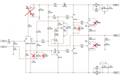
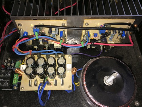
Here is my BAKSA. I made it around 3 to 4 years ago. I lost the schem but it is almost same schema with the one attached but without P2, C2B, C3B, C7, D3, D4
I used 2SA1837, 2SC4793 for drivers
2SC1819 for VAS
When I put 100nf 100VDC cap on C7 it sounds metallic (but I wasn't able to measure the amp back then, so I removed it.
R10 is 20R (instead of 100R), when I put 100R, the details and highs are reduced and veiled?
As for the sound it is very bassy (+punchy) and overpowers the mids.
Odd harmonics are dominant, maybe the reason why it is in my cabinet for a long time, maybe I need to modify it...
An externally hosted image should be here but it was not working when we last tested it.
An externally hosted image should be here but it was not working when we last tested it.
Attachments
You are right, Odd harmonics are dominant which is never good. Strong 3rd and 5th which spoils the party...
Normally Hugh's focus is on strong Even harmonics, 2nd and 4th and tries to have a non existant 5th.
Hopefully someone can help you.
BR,
Eric
Normally Hugh's focus is on strong Even harmonics, 2nd and 4th and tries to have a non existant 5th.
Hopefully someone can help you.
BR,
Eric
As you have deleted the bias adjustment for the input LTP, what is the bias current there? You can measure the voltage across R3 and calculate DC current using Ohm's law.
Odd harmonic distortion is really the outcome of non-linear device behaviour. The main source is crossover distortion but the state of balance of the LTP transistors determines whether 2nd and even harmonics will be removed, giving the appearance that odd harmonics are strong. Youve changed both in the schematic posted, by deleting the suck-out cap C7 and the bias adjustment P2 and filter cap C28. Did you remove these because of sound quality or just a lack of parts or the PCB didn't suit?
Odd harmonic distortion is really the outcome of non-linear device behaviour. The main source is crossover distortion but the state of balance of the LTP transistors determines whether 2nd and even harmonics will be removed, giving the appearance that odd harmonics are strong. Youve changed both in the schematic posted, by deleting the suck-out cap C7 and the bias adjustment P2 and filter cap C28. Did you remove these because of sound quality or just a lack of parts or the PCB didn't suit?
D
Deleted member 148505
I lost the schem but the implementation and values are more like on the attached below. I deleted suck out cap because I didn't like the sound, sounded like metallic. I reduced 100R to 20R because the details are lost. There is no bias adjustment P2 at that time if I remember correctly.
Attachments

D
Deleted member 148505
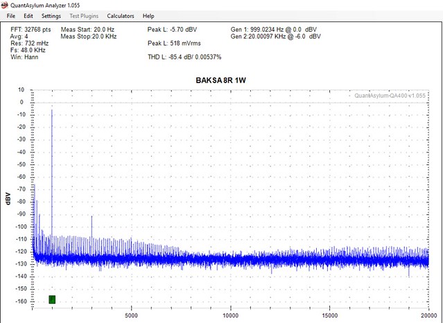
Ok so I modified my module with default values from the first post, so now it's almost the same.
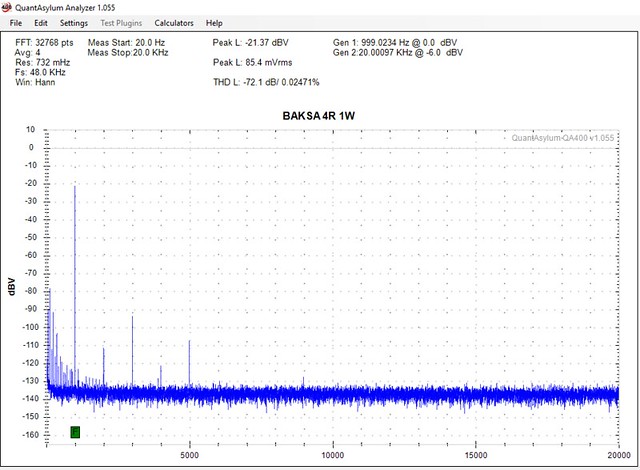
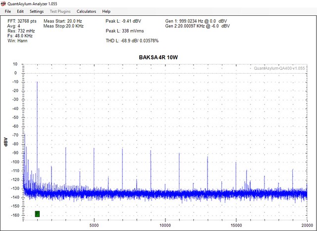
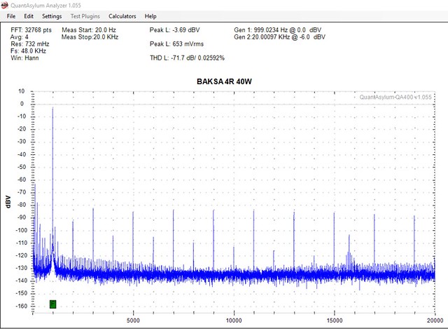
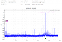
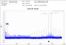
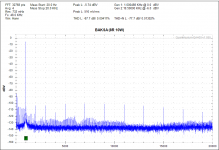
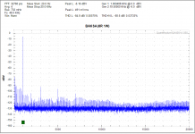
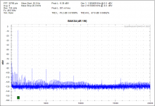
I removed phase lead. Added 100nf suck out cap. Here are the results.
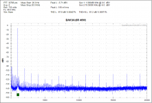
Good thing is that the THD is not increasing at higher power, always (more than) -85dB below the carrier.
I removed phase lead. Added 100nf suck out cap. Here are the results.
Good thing is that the THD is not increasing at higher power, always (more than) -85dB below the carrier.
Attachments
-
 4R 40W (IMD).PNG56.7 KB · Views: 174
 -
 4R 10W (IMD).PNG57.8 KB · Views: 168
 -
 4R 1W (IMD).PNG62.8 KB · Views: 168
 -
 8R 40W.PNG50.8 KB · Views: 186
 -
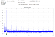 4R 40W.PNG51.9 KB · Views: 882
 -
 8R 10W.PNG54.1 KB · Views: 878
 -
 4R 10W.PNG54.3 KB · Views: 920
 -
 8R 1W.PNG54.1 KB · Views: 914
 -
 4R 1W.PNG53.5 KB · Views: 955
Last edited by a moderator:
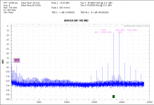
the third plot shows a little 2nd and lots of odd harmonics
The first and second show high levels of odd harmonics. Almost no even harmonics.
The sixth plot is the only one to show 2nd to 5th progressively lessening, but 7th, 9th, 11th etc are high again.
Any idea why these unusual proportions?
from post887
The first and second show high levels of odd harmonics. Almost no even harmonics.
The sixth plot is the only one to show 2nd to 5th progressively lessening, but 7th, 9th, 11th etc are high again.
Any idea why these unusual proportions?
from post887
Odd harmonics are dominant, maybe the reason why it is in my cabinet for a long time, maybe I need to modify it...
Last edited:
I lost the schem but the implementation and values are more like on the attached below. I deleted suck out cap because I didn't like the sound, sounded like metallic. I reduced 100R to 20R because the details are lost. There is no bias adjustment P2 at that time if I remember correctly.
This schematic is not even close to Mr. Hugh Dean's AKSA55, which is wide bandwidth (high slew rate) and H2 dominant. VAS transistor must have very low Cob, and compensation can not use only ordinary Miller compensation.
i changed the r15 resistor on the baksa schematic (the 150ohm bias resistor) to 2 strings of 1n4001 zeners. no reason behind it, just one a whim.
to my surprise the sound became softer, more to my liking.
but the drivers were getting too hot and one pair kept getting blown so i changed the zeners to 3 string and its been working fine so far.
what have i done and is it stable?
to my surprise the sound became softer, more to my liking.
but the drivers were getting too hot and one pair kept getting blown so i changed the zeners to 3 string and its been working fine so far.
what have i done and is it stable?
hi guys ,
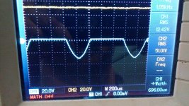
i made the amp based on the schematic provided , i have a problem some times during power on the positive half cycle of output sine-wave goes missing only the negative one stays also my bootstrap capacitor heats up a lot .it does not happen all the time but sometimes the positive half just goes missing any idea what could be wrong ??
i made the amp based on the schematic provided , i have a problem some times during power on the positive half cycle of output sine-wave goes missing only the negative one stays also my bootstrap capacitor heats up a lot .it does not happen all the time but sometimes the positive half just goes missing any idea what could be wrong ??
Capacitor heating might be due to oscillation.
Does your AM radio squeal when the symptom is present?
Does your AM radio squeal when the symptom is present?
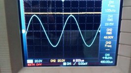
I just turned the amp on , intially as the amp was cold no issues no oscillatation , but as soon as it heated up a bit the positive half disappeared..???
And there is no oscillatation on the output , I have checked till 20khz ...it seems to be realted to amp heating up...and my supply rails are a bit high 50V becaue that the only trafo I have in hand...
And there is no oscillatation on the output , I have checked till 20khz ...it seems to be realted to amp heating up...and my supply rails are a bit high 50V becaue that the only trafo I have in hand...
Attachments
- Home
- Amplifiers
- Solid State
- Based on Hugh Dean's AKSA 55