Single 2n3904 Channel Switching Guitar Preamps, 5 circuit ideas shown, please comment
Here are some circuits I have been working on. This is sort of a right of passage that I've not been using op amps and I'm just trying to learn how much can be done with minimal parts and simple circuits. I was impressed by Joel Davisson's Easy Drive circuit for guitar distortion as I thought it sounded ok for how simple it was. Also the electra distortion can sound quite good depending on the diodes used and the filtering and so forth. Anyhow these circuits have already been done, but I thought if I ever used one as a preamp feeding into a power amp, it would be nice to switch to clean channel and have the volume the same. In other words, I'd like a simple preamp which can be switched from high drive/distortion circuit to simple preamp probably gain 5 or so. This is very simple to switch from one of these circuits by employing a DPDT, 3PDT switch etc. But I plan on switching tonestacks and other things in the circuit, so I don't want to make the switching too complicated. If so, you might as well just add separate signal paths for different channels and use more transistors or op amps.
My goals here are essentially:
1 Single 2n3904 transistor
1 Single pole switch
ability to trim distorted or clean levels is ideal
output impedance <100k, ideally <10k
minimal parts, it would be nice keep the parts list low enough to use panel mounted switches and pots and solder parts to them
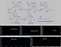
Here are the circuits I came up with and I'll describe the ideas behind them. I'm interested to hear from people about whether the ideas are good, bad, etc and why. I've named them just so its easy to refer to, and I have not really tested any of them fully. I'm looking to get feedback from people before I start testing them. (BTW I'm thinking you can replace the 2Meg resistor with 220ks and a .1u going to ground as shown on any of the circuits, for a little extra gain and tone shaping. This really does help the sound experimentally, although it doesn't do much in Spice Simulations.)
1) "Hot Link Electra" This is an Electra type distortion, but the diodes go to positive instead of ground. I've tested this by ear only on an electra distortion I built, I cannot tell the difference between the two audibly. There is a start up charging capacitor, so that when you power up it doesn't send a jolt to the output as the power slowly turns on. The capacitors around the clipping diodes should remain relatively well charge through the 50k resistor during either state clean or distorted. An LTSpice simulation showed that 50k was enough to isolate the drive and clean signals.
2) "Divided Rail Rode" This is based off a rudimentary distortion "Rail Rode" I made where the top of the signal clips at the voltage rail, and the bottom clips at the bottom of the transistor. This uses a voltage divider to knock the 9v down to around 1.5v so it clips at the rails. When you switch to clean channel the voltage divider is essentially removed from the circuit and the gain changes. This was basically one of the most rudimentary ways of making a clipper circuit that I could think of. It doesn't sound great, but if you replace the 2Meg with the circuit mentioned it helps quite a bit. (I have not tested the circuit with a 9 v battery and voltage divider, but with a 1.5v battery). This circuit is sensitive to having exactly 9 volts, but the voltage divider can be trimmed if needed.
3) "Flat Top" This is identical to the "Divided Rail Rode" circuit but instead of the top of the signal hitting the top voltage rail, it hits the bottom of a diode. I was guessing different power sources would clip differently and a diode might clip more consistently and possibly softer.
4) "Floating Floor" This circuit also clamps the signal, but instead of using a voltage divider, it raises the ground in the class A amp circuit from zero to 7.5 volts, leaving only 1.5v (9v-7.5v). It does this by using a zener diode (7.5 zener voltage). I ordered some zeners in the mail and will try this, I'm assuming this would work ok.
5) "Breakout". Like the old atari game where the pixel bounces off the ceiling and your platform at the bottom of the screen. This clips the bottom with a zener and the top with a diode. You could probably use multiple series of 1n4148 or 1n4001 etc or any combination to get the desired voltage drop needed at the positive rail. Basically you have 9v - zener voltage of 6.2v - (1.8 to 2.2 volts/~yellow LED voltage drop) = <1v
Please leave any comments, suggestions etc. I am looking to see if there are any basic problems with what I have done with these circuits.
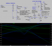
I included the circuits and what the distorted waveforms look like for each circuit. The clean channels look like sine waves.
Here are some circuits I have been working on. This is sort of a right of passage that I've not been using op amps and I'm just trying to learn how much can be done with minimal parts and simple circuits. I was impressed by Joel Davisson's Easy Drive circuit for guitar distortion as I thought it sounded ok for how simple it was. Also the electra distortion can sound quite good depending on the diodes used and the filtering and so forth. Anyhow these circuits have already been done, but I thought if I ever used one as a preamp feeding into a power amp, it would be nice to switch to clean channel and have the volume the same. In other words, I'd like a simple preamp which can be switched from high drive/distortion circuit to simple preamp probably gain 5 or so. This is very simple to switch from one of these circuits by employing a DPDT, 3PDT switch etc. But I plan on switching tonestacks and other things in the circuit, so I don't want to make the switching too complicated. If so, you might as well just add separate signal paths for different channels and use more transistors or op amps.
My goals here are essentially:
1 Single 2n3904 transistor
1 Single pole switch
ability to trim distorted or clean levels is ideal
output impedance <100k, ideally <10k
minimal parts, it would be nice keep the parts list low enough to use panel mounted switches and pots and solder parts to them
Here are the circuits I came up with and I'll describe the ideas behind them. I'm interested to hear from people about whether the ideas are good, bad, etc and why. I've named them just so its easy to refer to, and I have not really tested any of them fully. I'm looking to get feedback from people before I start testing them. (BTW I'm thinking you can replace the 2Meg resistor with 220ks and a .1u going to ground as shown on any of the circuits, for a little extra gain and tone shaping. This really does help the sound experimentally, although it doesn't do much in Spice Simulations.)
1) "Hot Link Electra" This is an Electra type distortion, but the diodes go to positive instead of ground. I've tested this by ear only on an electra distortion I built, I cannot tell the difference between the two audibly. There is a start up charging capacitor, so that when you power up it doesn't send a jolt to the output as the power slowly turns on. The capacitors around the clipping diodes should remain relatively well charge through the 50k resistor during either state clean or distorted. An LTSpice simulation showed that 50k was enough to isolate the drive and clean signals.
2) "Divided Rail Rode" This is based off a rudimentary distortion "Rail Rode" I made where the top of the signal clips at the voltage rail, and the bottom clips at the bottom of the transistor. This uses a voltage divider to knock the 9v down to around 1.5v so it clips at the rails. When you switch to clean channel the voltage divider is essentially removed from the circuit and the gain changes. This was basically one of the most rudimentary ways of making a clipper circuit that I could think of. It doesn't sound great, but if you replace the 2Meg with the circuit mentioned it helps quite a bit. (I have not tested the circuit with a 9 v battery and voltage divider, but with a 1.5v battery). This circuit is sensitive to having exactly 9 volts, but the voltage divider can be trimmed if needed.
3) "Flat Top" This is identical to the "Divided Rail Rode" circuit but instead of the top of the signal hitting the top voltage rail, it hits the bottom of a diode. I was guessing different power sources would clip differently and a diode might clip more consistently and possibly softer.
4) "Floating Floor" This circuit also clamps the signal, but instead of using a voltage divider, it raises the ground in the class A amp circuit from zero to 7.5 volts, leaving only 1.5v (9v-7.5v). It does this by using a zener diode (7.5 zener voltage). I ordered some zeners in the mail and will try this, I'm assuming this would work ok.
5) "Breakout". Like the old atari game where the pixel bounces off the ceiling and your platform at the bottom of the screen. This clips the bottom with a zener and the top with a diode. You could probably use multiple series of 1n4148 or 1n4001 etc or any combination to get the desired voltage drop needed at the positive rail. Basically you have 9v - zener voltage of 6.2v - (1.8 to 2.2 volts/~yellow LED voltage drop) = <1v
Please leave any comments, suggestions etc. I am looking to see if there are any basic problems with what I have done with these circuits.
I included the circuits and what the distorted waveforms look like for each circuit. The clean channels look like sine waves.
Attachments

1 transistor 3 band tone circuit, will it work?
Hi, thanks for looking. My main reason for posting was to get advice on the midrange control connected to the transistor's emitter.
(I was trying to design an easy 3 tone control with one simple transistor. I know the treble and bass controls work). I circled the midrange control. I ordered some inductors to try this out. Has anyone seen a design like this? Are there any problems with this idea that you recognize?
Basically its a simple LC resonator that has high impedance and at resonance. Its placed on the emitter to limit the gain of the circuit at resonance. It is placed in the emitter resistor position of a simple class A BJT amp. The circuit has an input impedance of about 100k and output impedance I'm thinking of < 5k.
Attachments
Simple guitar preamp with 1 transistor
Here is a simple preamp with channel switching. It has tone control for each channel. There is a "Drive" control which is unusual as it just bypasses the transistor from collector to emitter. (Basically the transistor is bypassed when the potentiometer is at zero, and at full resistance it forces the signal through the transistor. I did this originally with a pot, but then just allowed the ac to escape with a capacitor on the pots wiper, sounds better and better drive control) I did this because it allows simple wiring and a simple SPDT switch. It also has a "Post Volume" which is pretty rudimentary but better than not having it there. The tone controls are a bit interdependent on the volumes, but this doesn't seem to have much practical consequence as long as you understand how the circuit works (at low volumes the high treble cut is less pronounced). It actually sounds pretty good for what it is at full drive for how simple it is. Its similar to the Design your own distortion website and uses similar feedback as Joe Davisson's easy drive. Just thought I'd share this build if anyone was interested. The bright really only effects the clean channel audibly at least through a power amp and 1 12" speaker
Here is a simple preamp with channel switching. It has tone control for each channel. There is a "Drive" control which is unusual as it just bypasses the transistor from collector to emitter. (Basically the transistor is bypassed when the potentiometer is at zero, and at full resistance it forces the signal through the transistor. I did this originally with a pot, but then just allowed the ac to escape with a capacitor on the pots wiper, sounds better and better drive control) I did this because it allows simple wiring and a simple SPDT switch. It also has a "Post Volume" which is pretty rudimentary but better than not having it there. The tone controls are a bit interdependent on the volumes, but this doesn't seem to have much practical consequence as long as you understand how the circuit works (at low volumes the high treble cut is less pronounced). It actually sounds pretty good for what it is at full drive for how simple it is. Its similar to the Design your own distortion website and uses similar feedback as Joe Davisson's easy drive. Just thought I'd share this build if anyone was interested. The bright really only effects the clean channel audibly at least through a power amp and 1 12" speaker
Attachments

bass loss due to dc resistance of inductor
I am waiting to get inductors in the mail to try out. There were cheap inductors for 38 cents that had DC resistance of 300 ohms. A little more expensive for resistance of 90 ohms, then $2 a piece for 4.5 ohm inductors. I ran simulations on the 90 ohm and 300 ohms inductors to see the effects and there is bass loss. The 90 is not too bad with 2db loss. The 300 ohm is probably unacceptable for HiFi, but might be A-ok for a guitar amp as I've seen many tonestacks with some Bass loss in this range. I'm interested to see how these work out when I get them in the mail. Thanks for looking. I'm curious to see if this actually works and if its noisy. I've seen schematics for the cry baby wah but the inductors attached to the signal path not the emitter effecting the gain. So will repost after I test this circuit for anyone interested.
I am waiting to get inductors in the mail to try out. There were cheap inductors for 38 cents that had DC resistance of 300 ohms. A little more expensive for resistance of 90 ohms, then $2 a piece for 4.5 ohm inductors. I ran simulations on the 90 ohm and 300 ohms inductors to see the effects and there is bass loss. The 90 is not too bad with 2db loss. The 300 ohm is probably unacceptable for HiFi, but might be A-ok for a guitar amp as I've seen many tonestacks with some Bass loss in this range. I'm interested to see how these work out when I get them in the mail. Thanks for looking. I'm curious to see if this actually works and if its noisy. I've seen schematics for the cry baby wah but the inductors attached to the signal path not the emitter effecting the gain. So will repost after I test this circuit for anyone interested.
Attachments
built similar circuit that works
I used a series LC circuit at the collector rather than putting it at the emitter. I ran an electra distortion with 1n34as on the output then into this circuit. I ran that into a flat power amp with no filtering with 33k input impedance and then into a 12" speaker in an open back cabinet. These are the values I came up with tweaking by ear and you can see the simulated bode plot. Seems to work fine. Didn't sound noisy with this setup. I like this tone control because it has 100k input impedance and relatively low output impedance. I did not hear any radio transmissions etc with the inductor but it was shielded. I used an inductor with a 90 ohm dc resistance and added another 120 to it, because I wanted to design the circuit with the cheap readily available RF inductors which are 38cents and have 300 ohm resistance.
Next I am going to run a clean guitar signal into one of these arrangements and tweak everything by ear, caps, pots, bright etc. Thanks for looking. IF anyone knows of a similar circuit filtering the gain instead of the signal let me know. I've looked around but haven't found anything.
Attachments
Interesting as a learning tool, but in practice you are saving cents (transistors) and wasting Dollars (inductors).
It made sense in the old days because Tubes_were_EXPENSIVE , but not today.
It made sense in the old days because Tubes_were_EXPENSIVE , but not today.
Here is a version with all filters at collector, not tested.
Yeah I know what you mean about the inductors. They are even hard to find, but I found these 100mh inductors which were very common and relatively cheap that's what made me check this out. If I didn't find an abundance of cheap 100mh inductors I wouldn't have even tried this. but 38cents makes it more attractice.
Anything above 100mh, start to get really pricey and harder to find.
I like about the circuit that the output impedance isn't too high (can go into a 33k input power amplifier, or can easily be inserted in signal paths as input impedance is 100k and ouput is about 1.2k simulated). Below is another circuit I haven't tested yet, but I like this new idea because you can easily totally switch out or change the the tone control section/(and gain) at 1 single node.
I like simple circuits, but I have been building some preamps where you mount the switches and pots to a panel and then solder the parts to them. So I'm definitely looking for simple circuitry. Thanks for looking, any suggestions appreciated.
Thanks everyone for looking. I will repost after I have another build.
Attachments
"Active" Marshall tone control
This circuit is intended to be placed between an electra type distortion or any distortion (20k output impedance or so) and a power amp 22k input impedance.
The electra type distortion I used had a collector resistor of 20k an output Impedance of 20k and 2 1n34as as clipping diodes.
It has the advantage of not requiring a buffer after the tonestack and preamp.
In other words just insert this circuit after the distortion and before the power amp.
I used common inexpensive 100mh inductors which I have measured to be 240 ohms dc resistance.
Its a reasonable approximation to the Marshall tonestack in terms of the maximum and minimum values of tone controls.
It also by its nature has a gain of roughly 12 db.
This allows you to run an Electra Distortion (1n34as) into this circuit with an output voltage of about 1vrms.
Attachments
A Novice Asks
I don't understand how to use this active tone stack. Where does the input go? Are the resistors for BMT fixed or variable? Will this work in a tube amp?
colorcat.
I don't understand how to use this active tone stack. Where does the input go? Are the resistors for BMT fixed or variable? Will this work in a tube amp?
colorcat.
A little more information
Hi colorcat. First of all, one of the reasons I posted this is because I haven't seen a design like this before and its pretty simple so I like to share new ideas and I like simple circuits. I've been studying preamps for about a year now so I still have a lot to learn. Anyhow, what I'm getting at is if your new this is not a common design, however, I have a working amp with this circuit and to me it sounds fine.
I have redrawn the circuit to show it differently. A couple notes, the circuit is not expecting a very hot signal, probably average voltage of less than .3v, so something like a guitar level signal. The big peaks with the plucks can get suppressed or clipped on the negative part of the waveform. What I'm getting at is that there's a little bit of clipping probably going on that I cannot audible hear using a guitar level signal. Just an fyi.
The diagram I've reposted shows input output and 9v supply. The tone controls are potentiometers. (Note, when the bass pot measures low 0 ohms, the bass level is at the highest.)
1) The input impedance is about 100k ohms
2) The ouput impedance is about 3k ohms
3) It has a gain, probably something like 5, when I plug in a guitar directly to this circuit, I get about 1vrms out when strumming hard.
I really don't have any experience with tube amps, but basically, you have to make sure the signal is not too hot being fed into the circuit to avoid clipping, then you'll get about a 1vrms signal out.
Here is relatively simple amplifier I built that uses something very similar(I added a midrange sweep to the above circuit):
https://sites.google.com/site/garydavenportelectronics/2-transistor-simple-preamp-rebuild
It also shows a wiring diagram.
As far as input and output impedances, I'm not sure how new you are to this information or if you are already familiar with it, but basically when the signal goes from one section to the next, you are supposed to go up by at least 10xs impedance. So if you have a signal coming out of a circuit with ouput impedance of 10k, then it should be fed into a circuit with 100k or greater, etc. So really if you use this in a circuit, it needs an input not too hot, like about guitar level, input impedance 10k or less is ideal, fed into next section or power amp with 33k or so, expecting 1vrms.
Basically, you could build the attached circuit, plug your guitar directly into it, and feed it into a power amp for a clean guitar preamp, as long as the power amp is 33k input impedance or greater to avoid loss and is expecting up to 1vrms. I have changed values a little to make bass 500k pot and treble 10k pot tapers a little better. This changes eq curve a little different from that shown on prior post, but it sounded better to me and allows for a more common 500k pot to be used.
In the link with the 2 transistor preamp, I fed a distortion circuit into it that clips it to very low voltage with schottky diodes before being fed into the tone section.
Attachments

Last edited:
Thanks for the Info
Went to your site and added several things to my resource DB. The Pot Calc Tool is a very handy resource and a great reminder too. I've actually got a project at some point where I have to mod a Reverse Log Pot from 250 to 100K as I recall the values are.
Regards,
Colorcat.
Went to your site and added several things to my resource DB. The Pot Calc Tool is a very handy resource and a great reminder too. I've actually got a project at some point where I have to mod a Reverse Log Pot from 250 to 100K as I recall the values are.
Regards,
Colorcat.
Thanks, I need to actually do some more stuff with that pot calculator.
That pot calculator is not actually for "attenuation". It uses the outer lugs of the pot to turn it into a 2 node variable resistor and what your're seeing on the graph is the resistance between the outer lugs of the pot. On my list of things to do is make the more common arrangement where the top of the pot gets the signal, the bottom goes to ground and the wiper gets the output so to speak, like in the case of a volume pot or similar. When I get a little extra time I will update that page with some more common scenarios. Thanks for looking.
Keep in mind, I'm kind of new at some of this stuff, so I hope I haven't posted any thing erroneous.
Minimalistic Bare Bones 2 Transistor Guitar Preamp
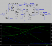
Here is a circuit I built today and figured I'd share it. I measured about 1v rms on the clean channel output going into a 33k ohm power amplifier. This is my attempt to make about the simplest preamp I can which sounds pretty good. So far this is the best I came up with. I think the EQ section is neat. It uses 1 inductor and 1 capacitor on the collector of a transistor and these get bypassed different ways to get bass, mid and treble controls. Because of this the midrange overlaps the bass and treble bands, but it seems usable. I set it so when the bass and treble are up, and mid is turned up and down, it resembles a marshall tonestack with the same settings roughly. I included a Bode plot.
Here is a circuit I built today and figured I'd share it. I measured about 1v rms on the clean channel output going into a 33k ohm power amplifier. This is my attempt to make about the simplest preamp I can which sounds pretty good. So far this is the best I came up with. I think the EQ section is neat. It uses 1 inductor and 1 capacitor on the collector of a transistor and these get bypassed different ways to get bass, mid and treble controls. Because of this the midrange overlaps the bass and treble bands, but it seems usable. I set it so when the bass and treble are up, and mid is turned up and down, it resembles a marshall tonestack with the same settings roughly. I included a Bode plot.
Attachments

A few simple errors
Caught a few errors, the wipers on the clean volume, post and master, are not supposed to be connected to one side of the pot. Made those corrections in this figure. I had them hooked up in the simulation so the signal would go through and forgot to erase them when posting sorry.
Caught a few errors, the wipers on the clean volume, post and master, are not supposed to be connected to one side of the pot. Made those corrections in this figure. I had them hooked up in the simulation so the signal would go through and forgot to erase them when posting sorry.
Attachments
Puzzled about driving a tone stack, any help appreciated.
Hi there, I was working on some guitar preamps, and I was thinking I would increase the gain and then run into a tone stack, then buffer, then power amp. The tone stack is a scaled down marshall type tone stack. Anyhow, I get this clipping in the design which I don't understand. In the figure I am showing 2 circuits. The first is just a signal 3v amplitude going through a tone stack and I vary bass mid and treble and here is the result at 1khz. Looks fine. But then, if I add a simple buffer just before the tone stack I get clipping. Can anyone explain why this does not work correctly?
Hi there, I was working on some guitar preamps, and I was thinking I would increase the gain and then run into a tone stack, then buffer, then power amp. The tone stack is a scaled down marshall type tone stack. Anyhow, I get this clipping in the design which I don't understand. In the figure I am showing 2 circuits. The first is just a signal 3v amplitude going through a tone stack and I vary bass mid and treble and here is the result at 1khz. Looks fine. But then, if I add a simple buffer just before the tone stack I get clipping. Can anyone explain why this does not work correctly?
Attachments

if I add a simple buffer just before the tone stack I get clipping.
You may be clipping the buffer's input with too much signal.
A 9V supply only allows a limited output swing as well.
Raise the buffer's simulated supply voltage and see.
Last edited:
Definitely 🙂
You are trying to pass a 3V **RMS** which swings almost **9V PP** through a buffer which is fed by puny 9V.
As a side note, you did not assign internal impedance to signal generator, while real world ones will have a significatve one.
And at the buffer, positive signal half comes from the transistor, which can source a lot of current, easily 5mA and maybe 10mA, but lower half is pulled through a 3k3 resistor, which can sink best case some 1.5mA and that at very small signal levels, once negative signal peak is 0.5V from ground it can only sink 0.5V/3300 ohms= 0.15mA .... nothing!!!
So under load (the tone stack) the lower half clips early because of current starving.
One problem with simulators is that they can show you what happens ... but can´t tell you *why*.
Or to put it in correct perspective: a Simulator is a useful tool, but does not replace learning Theory.
- Status
- Not open for further replies.
- Home
- Live Sound
- Instruments and Amps
- Simple 2 transistor panel mount guitar preamp.