a Simulator is a useful tool, but does not replace learning Theory.
I wish more people understood this. Lots of today's students do not.
> Simulator is a useful tool, but does not replace learning Theory.
Fie on theory. Sometimes "common sense" is wanted.
First: split the system to find the problem. No water at the upstairs bathroom? Check in the kitchen, garden tap, street-meter. Here, a waveform "in the middle", without the tonestack, would locate where it wasn't getting through, and take the stack out of the problem.
Second, you can't put a 8-foot truck through a 6-foot gate. I never know if a sim's "3V" is RMS, peak, or p-p.... put a tape-measure (or sim meter) on it and find out! If this is indeed a signal which needs 8.48V to clear both sides, then a 9V supply smells like a tight fit. I'd expect scrape-marks on the truck or gate.
The point about source impedance is also very good. SPICE sources can power-up whole cities and nations (10^32 Watts). In this case it can easily force-through this buffer, on the up-swing. Like a 8-foot *armored* truck which WILL get through the 6' gate. Or if the gate was tubing one side and concrete the other, then one side would get through. A real guitar with 5K-50K impedance would clip on the top also.
Thanks everyone for the help. I really didn't intend to put 3v through the tonestack, but I was sort of pushing the envelope so to speak to see the limits. I did notice one thing in the simulations anyhow, is if I scale up the tonestack to a higher impedance, it will clip a lot less. Additionally, just playing with a signal source of higher voltage (2-3 v peak for example), you can prevent clipping if your next stage after the buffer is a bit higher than the emitter resistor. For example, the emitter resistor above is 3.3k. If your next stage (tonestack, whatever) is a bit above this, say 6.8k or so, it can take a higher signal without clipping. This intuitively makes sense after the above explanations. The great benefit of a bjt buffer is the low output impedance in the 100's of ohms usually (Depends on source impedance as noted), but to send higher voltages, I think you really have to look at the emitter resistance and go above that if you expect to drive it with any higher voltages. The tonestack above is very low impedance.
> The tonestack above is very low impedance.
Yes.
Without running the whole math, assume all caps go "short" near the top of the audio band. R22+R27 is near 2.2K.
The BJT may pull "up" with near 30 Ohms (or hundreds counting source impedance), but pulls-down as 3.3K. This will not slam a 2.2K load anywhere near the negative rail. And is much larger than the 1K in your upper sim.
I'm not sure I'd like those tonestack values. They are not much like a scaled Fender stack. The curves are very mild. The value-scaling ranges from 5X to 100X. If you are happy, I'm happy; but it seems "tame".
Attachments

I basically did a scaled down version of the marshall tone stack. I used the source resistance as 100 ohms though.
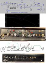
Here is a project I finished yesterday. My idea was, if you have a blown guitar amp, and you want to do a quick and easy rebuild, just take some pots, jacks and solder a small amount of components onto them to turn the faceplate into a functioning preamp. This of course can be fed to any amp module, or can just use as a preamp if you wanted. There is one less common part, but it makes the build a lot easier, a 200mh inductor. They are actually not hard to find or expensive, you probably just don't have them lying around. 2 100mh in series are very common and work fine. For as simple as it is, it doesn't sound to bad. I put a 600hz notch with similar depth and range as a marshall tone stack.
Approximate Specifications:
9 VDC power supply
Input impedance 100k
Output impedance about 2-4k (before 20k master volume as shown)
Output voltage about 1vrms
Nominal Input Level -14 dBV, 200mV RMS
Maximum Input Level -6 dBV, 500mV RMS
Approximate Specifications:
9 VDC power supply
Input impedance 100k
Output impedance about 2-4k (before 20k master volume as shown)
Output voltage about 1vrms
Nominal Input Level -14 dBV, 200mV RMS
Maximum Input Level -6 dBV, 500mV RMS
Attachments
- Status
- Not open for further replies.