One thing for sure: You can't safely use devices with a Vce rating of 100V as drivers in an amplifier that is fed from about +/-77V, the DC voltages after rectifying your 55-0-55VAC. Addidtionally, these TIP's aren't the most fastest ones. Perhaps you may ask for MJE15034/35's?
Best regards!
Best regards!
One thing for sure: You can't safely use devices with a Vce rating of 100V as drivers in an amplifier that is fed from about +/-77V, the DC voltages after rectifying your 55-0-55VAC. Addidtionally, these TIP's aren't the most fastest ones. Perhaps you may ask for MJE15034/35's?
Best regards!
i used tips with 36-0-36 AC it works with good quality but not as powerful as the mje's on B500 it happened that suppliers here had stopped selling them, only the mje340/50 are on stock
any way i may deal with ebay and ali later...
thanks for the support
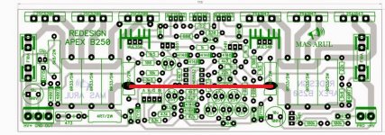
Apex B250
I just finished two B250, and tried to power up both of them and no one works. I connected the signal ground to power supply grround, dummy load 4 R, signal generator, and power supply +-80 volt. Nothing....everything it's cold, but no signal at output. What it's wrong or this pcb have some errors?

I just finished two B250, and tried to power up both of them and no one works. I connected the signal ground to power supply grround, dummy load 4 R, signal generator, and power supply +-80 volt. Nothing....everything it's cold, but no signal at output. What it's wrong or this pcb have some errors?
do you have any voltages at the output?
Vac or Vdc?
No AC or Dc at ouput. Only thing that I saw, are some spikes at output, on oscciloscope when high signal was applied to input.
First time when I power up, I used a bulb that glow very low, and instead fuse, two rezistor 100 R was used, and after that I put The fuses. I verified once again all semiconductors, and everythiong seems ok, I replaced ne5532 with another one. Nothing....Looks like the output is completely isolated from the power.
No one made this version of pcb? maybe there are a errors, I dont know maybe a wrong transitor placement, I already check and I didn't find any mistake. All other Apex schematics work from the first time for me. This one...it's strage for me...two pcb...and no one work....I recheck al resistors,etc.even with a broken front end I would expect some output voltage.
Use the Matching Schematic and post all the Measured DC voltages as a Start.
" I dont know maybe a wrong transitor placement, I already check and I didn't find any mistake " My Ouija Board does not work Online.
" I dont know maybe a wrong transitor placement, I already check and I didn't find any mistake " My Ouija Board does not work Online.
I just finished two B250, and tried to power up both of them and no one works. I connected the signal ground to power supply grround, dummy load 4 R, signal generator, and power supply +-80 volt. Nothing....everything it's cold, but no signal at output. What it's wrong or this pcb have some errors?
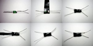
Is there wire jumper on your pcb?
Attachments
Yes sir, I put that wire.Is there wire jumper on your pcb?
Last edited:
Humbug ???
Attachments
Hi every body
i need the latest schematic for SIR Apex B500 with limiter and protection
i want create an smd pcb for it.
thank you
i need the latest schematic for SIR Apex B500 with limiter and protection
i want create an smd pcb for it.
thank you
Hi everyone may i ask if i can use BC639 instead of BC517 on B500P
thanks
sam.
No. The BC517 is darlington, the BC639 is just simple npn.
Sajti
higher rail problem
my b500 is working very good at 55 0 55 v dc ..Nice audio output ..but when I increase dc voltage to 75 0 75 v...it's clipping very fast i e at very lower audio level the clipping indicator glowing red and speaker sound flipping ....when I change bias resistor from 1.2k to 330ohms clipping occurs at higher level of Audio .but at clipping point the sound becomes distorted ...so what's the problem ??and what is the actual bias resistor for b500 tef at 75 0 75v dc ??
my b500 is working very good at 55 0 55 v dc ..Nice audio output ..but when I increase dc voltage to 75 0 75 v...it's clipping very fast i e at very lower audio level the clipping indicator glowing red and speaker sound flipping ....when I change bias resistor from 1.2k to 330ohms clipping occurs at higher level of Audio .but at clipping point the sound becomes distorted ...so what's the problem ??and what is the actual bias resistor for b500 tef at 75 0 75v dc ??
my b500 is working very good at 55 0 55 v dc ..Nice audio output ..but when I increase dc voltage to 75 0 75 v...it's clipping very fast i e at very lower audio level the clipping indicator glowing red and speaker sound flipping ....when I change bias resistor from 1.2k to 330ohms clipping occurs at higher level of Audio .but at clipping point the sound becomes distorted ...so what's the problem ??and what is the actual bias resistor for b500 tef at 75 0 75v dc ??
now working perfectly actually one mje15032 damaged due to inrush current flow .. actually I connect 1.5 kva 50 0 50 v ac transformer without soft start and inrush current damaged small components..
- Home
- Amplifiers
- Solid State
- 500W PA amplifier with Limiter