Rock'ola 1422.
I took a '46 jukebox amp with a bad IT and replaced the IT with an ax7 splitter/ au7 driver circuit. The two tubes use 15.2mA of current from the PT at idle. The amp has been tested, and requires more gain to produce sufficient volume.
When stock, and at idle, the amp draws ~185mA through a 5U4G rectifier. The AC input is about 385VAC, with the rectifier connected and loaded by the circuit, and output at C1 is 430VDC.
With the extra ax7/au7, the amp idles at about 200mA. I'm concerned about a 70 year old XF... the stakes are high on this amp.
Here's where the current was spent:
105mA = (2) 6L6
65mA = an interesting 5k ohm field coil added to the amp that draws from the 6L6 screen grid and sends to ground.
3.5mA = single triode (6J5) first preamp stage
15.2mA = Supplemental ax7/au7 circuit, now referred to as "The Card", as it was build on protoboard.
** FWIW, the amp has a 6J5 for the first preamp tube, which is a single triode version of the 6SN7. To experiment with the options available, I rewired this socket and installed a 6SN7. The extra gain is fantastic, but I have to correct some grid values in the ax7/au7 stages to keep them from clipping. The extra current draw is between 4 and 7mA at idle for this extra triode. In testing, I used a bench top tube PS to supply juice to this triode, as I'm not sure that it should be added to the Rock'ola PS yet.
Would anyone suggest an alternative to the 6j5/6SN7 swap? The ax7/au7 was built from a schematic, so the plate resistors and plate curves are already established. They could be changed, but this might be a pain. This amp has a Bax style TS that causes a good drop in gain as well.. The TS is between the "6J5" socket (first preamp tube) and the ax7/au7. Thanks.
One more thing, If the 6SN7 is a good idea, I could (potentially) add a small 300V PS inside the chassis.
replace the rectifier with a ss set-up. If you feel the need to retain the rectifier for aesthetic purposes, just run its heater and use the ss diodes for rectification.
An SL7 will give you greater gain up front at much lower anode currents than an SN7. It will mess with your bax set-up however.
An SL7 will give you greater gain up front at much lower anode currents than an SN7. It will mess with your bax set-up however.
It's hard to beat the 6J5/6SN7 triode for linearity and an additional PSU for the front end is reasonable.
A quick try to keep things more or less as they are is 10M45S CCS, instead of resistive, loading the 6J5 voltage amplifier. Some additional gain will be realized. If it's enough, I can't say.
A quick try to keep things more or less as they are is 10M45S CCS, instead of resistive, loading the 6J5 voltage amplifier. Some additional gain will be realized. If it's enough, I can't say.
It will mess with your bax set-up however.
Aardvarkash10, the SL7 uses much less current and has a mu of 70, that looks very appealing! How will it mess up the bax TS? I'm guessing it trades voltage gain for power/current gain, so I wouldn't have the extra current to drive through the TS with good results.
About the limit of the rectifier, I have no experience with how rectifier current changes during an amp's operation. Does the current go up "significantly" during the dynamic operation of the amp?
My first priority is to KEEP THE PT IN A SAFE OPERATING RANGE, as it cannot be easily replaced. My second priority is to understand how close the amp can be run, at idle, to the max rectifier current and keep it's reliability.
TA,
The little ZVN0545A MOSFET may be part of a solution. A 6SL7 or 5751 section runs with an approx. 1 mA. IB. DC couple a ZVN0545A source follower to the voltage amplifiers plate. A 2 mA. or so drain current will get you well under a 1 Kohm O/P impedance and that should drive your tone controls quite adequately.
The tweaked RCA phono preamp I've uploaded several times shows the technique.
BTW, the net gain of the buffered triode will increase. 😉
If you are concerned about the transformer, I would recommend operating off a variac, or add a buck transformer to reduce the line voltage to a max of 115VAC at the primary of the original transformer.
Aardvarkash10, the SL7 uses much less current and has a mu of 70, that looks very appealing! How will it mess up the bax TS? I'm guessing it trades voltage gain for power/current gain, so I wouldn't have the extra current to drive through the TS with good results.
You got it - and Eli gives the solution.
Thanks Eli,
I read your posts with interest. The mosfet would function the same as a cathode follower (current driver)? The mosfet would also use less current than a triode (second half of 6SN7) when doing the same task? What specs are most important to have in a Mosfet Source Follower? How much current would the triode use as a cathode follower?
With a single 6j5 triode, a 13mV at the grid becomes a 16mV (unloaded) signal after the TS, and about 8mV (loaded). A current driver before the TS sounds like the best option 🙂😛😀
Thanks Eli,
I read your posts with interest. The mosfet would function the same as a cathode follower (current driver)? The mosfet would also use less current than a triode (second half of 6SN7) when doing the same task? What specs are most important to have in a Mosfet Source Follower? How much current would the triode use as a cathode follower?
With a single 6j5 triode, a 13mV at the grid becomes a 16mV (unloaded) signal after the TS, and about 8mV (loaded). A current driver before the TS sounds like the best option 🙂😛😀
Tubes, FETs, and BJTs; all can be used as buffers, AKA voltage followers. The corresponding names are cathode follower, source follower, and emitter follower. Tubes and FETs "play nicely" with each other.
The single most important parameter in selecting a FET for mating to a triode is a low and stable reverse transfer capacitance. Even a wimp, like the 6SL7 triode, has no problem driving the ZVN0545A's tiny capacitances. 😀
The FET is a "no brainer" to set up and it is not subject to heater to cathode potential limit trouble; nor does a FET consume filament current. IMO, the FET is best for this job. Field experience shows that a 12 V. protective Zener diode should be connected from the plate side of the gate stopper resistor to the FET's source electrode. Start up conditions are different than "steady state". Remember, the FET is instant on and the triode needs time to start conducting.
FWIW, I suggest you make 2 adapters from Noval sockets and Octal plugs. one adapter operates system #1 of a 5751 and the 2nd adapter operates system #2. The 5751 triode is "equivalent" to the 6SL7 triode and the 2 adapters allow you to get "milage" out of both tube sections, without wasting heater current.
BTW, always wear an anti-static wrist strap, when working with MOS semiconductors. Once the part is soldered into place, it's safe.
Last edited:
Rock'ola 1422.
65mA = an interesting 5k ohm field coil added to the amp that draws from the 6L6 screen grid and sends to ground.
What is this circuit? Speaker?
What is this circuit? Speaker?
It makes sense for it to be a field coil speaker. The OP stated he's working with a 1946 jukebox amp. AlNiCo is a post WW2 development. The speaker predates permanent magnets of adequate flux strength.
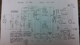
'46 Rock'ola Model "O" 1422, heavily modified.
(Original Schematic Below)
Looks like you have the option to ditch the field coil speaker and repalce it with a PM type. Also, on the ax7/au7 stage you're building, is that 2 full tubes or a dissimilar triode type?
So the field coil adds a supplemental "electro-magnet" to enhance the speaker function?
Thanks again Eli! And Thanks to everyone else as well!!
^Two other issues with the amp:
1. Excessive Hum/ripple on B+/C1 cap to plates of 6L6. C1 is already maxed out at 40uF for an LC filter following the 5U4G. Ripple is excellent from the screens onward towards the preamp. Every stage is decoupled with an RC, with the RC rolloff points below 6Hz. About 100uF in total throughout the power supply. Much of the ripple is cancelled out in the OT. It is definitely 120Hz, and every cap in this amp is new.
2. Excessive noise around 7500-12kHz. Reminds me of "cap noise" or noise caused by flow of electrons. All resistors are new, I will measure tube currents.
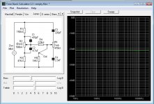
3. Bax treble control squeals and makes shrill noise when control is past ~60%. I think a 500k log pot from CTS has been used for each of the Bass and Treble controls. Below is the TS schematic. Shielded wire has been used for output of signal, but input is 8" of non-shielded HT supply running from 6J5 to tonestack. Quite a jump. Does output loading or input loading affect the stability of a TS? In other words, what is likely to cause a small HF oscillation to "creep" along a sine wave (post-TS) when the treble control is adjusted?
Thanks again Eli! And Thanks to everyone else as well!!
^Two other issues with the amp:
1. Excessive Hum/ripple on B+/C1 cap to plates of 6L6. C1 is already maxed out at 40uF for an LC filter following the 5U4G. Ripple is excellent from the screens onward towards the preamp. Every stage is decoupled with an RC, with the RC rolloff points below 6Hz. About 100uF in total throughout the power supply. Much of the ripple is cancelled out in the OT. It is definitely 120Hz, and every cap in this amp is new.
2. Excessive noise around 7500-12kHz. Reminds me of "cap noise" or noise caused by flow of electrons. All resistors are new, I will measure tube currents.
3. Bax treble control squeals and makes shrill noise when control is past ~60%. I think a 500k log pot from CTS has been used for each of the Bass and Treble controls. Below is the TS schematic. Shielded wire has been used for output of signal, but input is 8" of non-shielded HT supply running from 6J5 to tonestack. Quite a jump. Does output loading or input loading affect the stability of a TS? In other words, what is likely to cause a small HF oscillation to "creep" along a sine wave (post-TS) when the treble control is adjusted?
Attachments
20to20, 4 triodes in total. The 12ax7 looks to be gain/phase inversion, then sends the signal through a HP into the 12au7.
So the field coil adds a supplemental "electro-magnet" to enhance the speaker function?
It actually creates the magnet from a dead chunk of steel or whatever it's wrapped around. The voice coil is attached to the cone. So all you need is to pull and then jumper that big plug for power and add an external speaker on the screw terminals. Looks like there is some other jumper plug you have to select to use those external connections for the impedance match.
Last edited:
Hard steel will become permanently magnetized. An electromagnetic driver uses soft iron that demagnetizes, when the current is turned off. I'm guessing that really low carbon content cold rolled steel will not permanently magnetize.
FWIW, home made toys and compasses are made by stroking (single direction) a sewing needle on the pole of an existing magnet.
It was common for 1930s radios to employ CLCLC PSU filters, where the 2nd inductor is the field coil of the speaker. Back then, 8 μF. was a seriously large capacitance.
FWIW, home made toys and compasses are made by stroking (single direction) a sewing needle on the pole of an existing magnet.
It was common for 1930s radios to employ CLCLC PSU filters, where the 2nd inductor is the field coil of the speaker. Back then, 8 μF. was a seriously large capacitance.
> really low carbon content cold rolled steel will not permanently magnetize.
It "will", to the extent that you can pick up pins and small paperclips.
A LOUDspeaker needs STRONG field. Can't pull it off the refrigerator. Tungsten steels and similar were OK for telephones, and some armature speakers, but "real" speakers used soft "dead" iron wrapped with a winding and fed big DC. Often half or more the power of the amplifier's output.
Alnico was not an alternative, as said, until the post-WWII years. J B Lansing was very enthusiastic about the Alnicos. (Alnico came out of work done in 1931, but it was never cooperative. It was of use in the War Effort, notably early Magnetrons, but not available in commerce until after.)
Magnet Energy/ PM history
History of Permanent Magnets
Question about Tonestack layout, antenna for 120Hz
Must be 18 or older to view this picture, because the Tone Stack is Dirrrty!
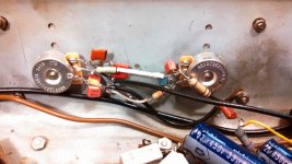
The second photo is the schematic of the tone stack. Why is it that the conductor that transfers signal directly from the coupling cap to the treble cap introduces much more 120Hz noise than if it was non-shielded? I have installed this wire both ways, shielded and non-shielded, and there is more than twice the peak voltage entering the signal path. Is the cable "capacitive coupling" the signal from the shield to the center conductor? Is there anything I can do?
Orientation: The bass pot is on the right, treble pot on the left. Bottom left you will see two wima's in parallel, this is the treble cap. Originally, the bass pot was mounted with the terminals facing right, and the cabling was much longer. I rewired with the goal of stopping a HF oscillation that occurs when the treble pot moves past 60% of full rotation in the "treble boost" direction.
I'm going to post this message, then build a faraday cage around the sucker, using the four screws in the photo to mount the metal cover. I've got to finish this amp tonight, and I'll do whatever it takes, but I'd also like to learn how to prevent real issues like this from an electrical standpoint (ie: without tin shears!)
I think the leads are still too long, and the treble-lead is the most troublesome. I moved the 150k and 47k resistors right to the edge of the high impedance soldering point, the same way that we would mount a grid stopper. I wasn't sure which side the 220k should go on. Some of the caps, the non-wima's, are sensitive antennas, but they are the only caps I have with the value I require. I have tested the cases of the pots by connecting a ground lead to their shell, and it appears to have no effect. I will run a buss wire from both shells to ground.
Must be 18 or older to view this picture, because the Tone Stack is Dirrrty!
The second photo is the schematic of the tone stack. Why is it that the conductor that transfers signal directly from the coupling cap to the treble cap introduces much more 120Hz noise than if it was non-shielded? I have installed this wire both ways, shielded and non-shielded, and there is more than twice the peak voltage entering the signal path. Is the cable "capacitive coupling" the signal from the shield to the center conductor? Is there anything I can do?
Orientation: The bass pot is on the right, treble pot on the left. Bottom left you will see two wima's in parallel, this is the treble cap. Originally, the bass pot was mounted with the terminals facing right, and the cabling was much longer. I rewired with the goal of stopping a HF oscillation that occurs when the treble pot moves past 60% of full rotation in the "treble boost" direction.
I'm going to post this message, then build a faraday cage around the sucker, using the four screws in the photo to mount the metal cover. I've got to finish this amp tonight, and I'll do whatever it takes, but I'd also like to learn how to prevent real issues like this from an electrical standpoint (ie: without tin shears!)
I think the leads are still too long, and the treble-lead is the most troublesome. I moved the 150k and 47k resistors right to the edge of the high impedance soldering point, the same way that we would mount a grid stopper. I wasn't sure which side the 220k should go on. Some of the caps, the non-wima's, are sensitive antennas, but they are the only caps I have with the value I require. I have tested the cases of the pots by connecting a ground lead to their shell, and it appears to have no effect. I will run a buss wire from both shells to ground.
Attachments

- Status
- Not open for further replies.
- Home
- Amplifiers
- Tubes / Valves
- Reaching max Rect. Current and amp needs more gain.