I guess, your test setup consists of DUT and an analysis system. No problem at all. But in conjunction with grounded devices connected to DUT will often cause problems (filter caps from earth ground to circuit ground etc.).
If they only went from circuit ground to PE that wouldn't be a biggie. The fun comes in when they go from both mains lines to PE and PE is tied to secondary-side ground (either hard or via a cap in the nF)... and then the supply is operated with a 2-conductor mains lead with no PE connection. (No kidding. There must be countless SMPS like that out there.) Et voilà, secondary-side ground is pulled towards half the mains voltage via something nF-ish, so the resulting leakage currents will gladly make their way towards PE wherever they can.
Granted, it would be an easy fix - make sure you have PE available and reference your mains filter to that, it doesn't have to be used for anything else (but would probably have a nF-ish cap to secondary-side ground for EMI reasons). Still not as little PE coupling as a good xfmr (with shield winding), of course.
Granted, it would be an easy fix - make sure you have PE available and reference your mains filter to that, it doesn't have to be used for anything else (but would probably have a nF-ish cap to secondary-side ground for EMI reasons). Still not as little PE coupling as a good xfmr (with shield winding), of course.
The Mean Well bricks are Class 2, so there's no electrical connection between the primary and secondary sides. They have built-in mains filters.
I'd still argue that if I don't measure any crap on the amplifier output, there is no issue. At least no technical issue. That doesn't mean that there isn't a psychological (perception) issue or religious (belief) issue. I suppose eventually progress will be accepted. 🙂
Tom
I'd still argue that if I don't measure any crap on the amplifier output, there is no issue. At least no technical issue. That doesn't mean that there isn't a psychological (perception) issue or religious (belief) issue. I suppose eventually progress will be accepted. 🙂
Tom
I had some examinations of the Meanwell bricks last year and I saw a cap between primary and secondary side of the transformer. That causes a lot of trouble. Hum, noise, little electrical shocks...
Despite all these imperfections in the design of a ac to dc converter from a pretty big company like Meanwell and the fact the the measured performance is low in noise and THD, do you still think it really matters?
Even really inexpensive no name brand made in china DC to DC converter like an MT306 ($0.40 ea) can work very well. They switch at 1.2MHz. Well above the audio band so very steep filters can be used.
Even really inexpensive no name brand made in china DC to DC converter like an MT306 ($0.40 ea) can work very well. They switch at 1.2MHz. Well above the audio band so very steep filters can be used.
Last edited:
Maybe diyralf did not hammer his point home well enough: You are measuring splendid performance when using an audio analyzer with the luxury of galvanically isolated inputs and outputs. But what'll happen when you connect a source that is PE referenced, maybe using a cable of less than desirable shield resistance?
If it holds up, fine. I wouldn't expect anything too major anyway, maybe it's just measurable and irrelevant in practice. You just can't tell beforehand. Nothing more, nothing less.
My impression of Meanwell supplies so far has been that they are "good enough" - they get the job done, pass regulations and don't blow up in your face, but they're definitely built down to a price. Don't expect the last word in EMI filtering and such. Some of their old conventional universal supplies had some pretty nasty transformers, too. I've got a 3/6/9/12 V 1200 mA regulated job that draws 4 W in idle - no, not VA, watts. Plus about twice the output power @12 V if memory serves. And it hums like an old model railroad transformer.
I don't believe the inputs on the APx525 are galvanically isolated. The BNC connectors on the single ended inputs (used for measuring the HP-1) connect to chassis ground, which I'm 99.99 % certain connects to mains/protective earth.
I've had no issues with the Mean Well bricks. I can't speak for their quality levels in the past of the quality of their other product lines, as I've only been using them for about a year. I've had no complaints and have noticed no irregularities myself.
I do follow the regulators up with an CLC filter and a linear regulator to ensure that the supply voltage is as quiet as can be in the HP-1.
FWIW: MiniDSP includes a Mean Well brick with their MiniDSP 4x10HD. It seems to perform quite well as evidenced by the measurements I show on my website.
Tom
Last edited:
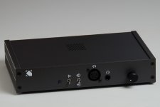
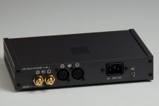
As promised, here are the results of the chassis colour survey. Graphite seems very popular. It also seems people are either "black" or "anything but black", indicated by the rather large slice of "graphite" in the graphite vs black pie chart.
The next stack of enclosures will have a couple (2 of 10 probably) in blue and the rest (8 of 10) in graphite.
Tom
The next stack of enclosures will have a couple (2 of 10 probably) in blue and the rest (8 of 10) in graphite.
Tom
Attachments

Hi Tom,
Your design looks great and i really like your series "Taming the LM3886", i have learnt a lot from it. I have some question about your design:
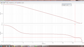
1. Which model of the LME49600 did you use to simulate? I use the model by TI and the loopgain response doesn't change when i change the value of Cload, the Buf634 come with the Tina installation simulate well
2. One of the most critical point was emphasized in your design is that the amp stable even with 10nf load but in normal situation, the headphone cable is only about hundreds pf, so this is only advantage at some extreme case?
3. When i simulate amp with and without the compensation capacitor, the THD is often higher when compensation is used, even double the THD. Do you observe this in real measurement?
4. About stability, amp oscillate when the phase is -180 degree at frequency loopgain = 0 but this only happen when there is a signal at the input so the output go to infinite and oscillate, if there is no input signal at that frequency, amp won't oscillate, right?
Thanks!
Your design looks great and i really like your series "Taming the LM3886", i have learnt a lot from it. I have some question about your design:
1. Which model of the LME49600 did you use to simulate? I use the model by TI and the loopgain response doesn't change when i change the value of Cload, the Buf634 come with the Tina installation simulate well
2. One of the most critical point was emphasized in your design is that the amp stable even with 10nf load but in normal situation, the headphone cable is only about hundreds pf, so this is only advantage at some extreme case?
3. When i simulate amp with and without the compensation capacitor, the THD is often higher when compensation is used, even double the THD. Do you observe this in real measurement?
4. About stability, amp oscillate when the phase is -180 degree at frequency loopgain = 0 but this only happen when there is a signal at the input so the output go to infinite and oscillate, if there is no input signal at that frequency, amp won't oscillate, right?
Thanks!
Attachments
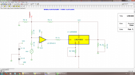
I agree that the model provided by TI is worthless. I started with that and then took measurements of the LME49600 using my HP 3577A network analyzer to develop my own AC model for the LME49600. I backed that up with quite a bit of prototyping to ensure that the amp would be stable across a wide range of load capacitances. As I'm sure you'll find if you build the circuit as shown in your sim sheet, the LME49600 will oscillate quite happily in the 75-150 MHz range. I finally got to use my 2.9 GHz spectrum analyzer for the purpose I bought it for ... to detect oscillation in amps. 🙂
My stability claims go beyond "stable at 10 nF". Perhaps I should communicate that better. The HP-1 is stable with 0 pF to 10 nF with no holes in the range. It's easy to build a system that's stable at 10 nF but isn't at 100 pF. You have to make sure that the amp is stable in the entire range. Otherwise you'll end up in a situation where the amp oscillates when a user plugs in a 3 m extension cable but not when they use the 5 m extension cable or the headphones plugged directly into the amp.
Simulating THD is challenging. You gotta know how FFT works and how to set the simulator step size and FFT window to get realistic results. Then again, as you point out, the model of the LME49600 that you get from TI doesn't model much, so would you trust it for THD?
It was a fun challenge to get it all working well. It was definitely not a plug-n-play design. Precision circuit design has a funny way of being that way. It looks easy on the surface but contains a lot of complexity under the hood.
Tom
Last edited:
Simulation of THD is not challenging but pointless in this case, since the model TI provides is not a transistor level model.
I guess, your test setup consists of DUT and an analysis system. No problem at all. But in conjunction with grounded devices connected to DUT will often cause problems (filter caps from earth ground to circuit ground etc.).
If you have ground loop problems, just make an RCA to XLR adapter cable that connects to + and - (and leave the shield unconnected)
Simulation of THD is not challenging but pointless in this case, since the model TI provides is not a transistor level model.
Which is why I went with a build-and-measure approach for THD.
Tom
I agree that the model provided by TI is worthless. I started with that and then took measurements of the LME49600 using my HP 3577A network analyzer to develop my own AC model for the LME49600. I backed that up with quite a bit of prototyping to ensure that the amp would be stable across a wide range of load capacitances. As I'm sure you'll find if you build the circuit as shown in your sim sheet, the LME49600 will oscillate quite happily in the 75-150 MHz range. I finally got to use my 2.9 GHz spectrum analyzer for the purpose I bought it for ... to detect oscillation in amps. 🙂
My stability claims go beyond "stable at 10 nF". Perhaps I should communicate that better. The HP-1 is stable with 0 pF to 10 nF with no holes in the range. It's easy to build a system that's stable at 10 nF but isn't at 100 pF. You have to make sure that the amp is stable in the entire range. Otherwise you'll end up in a situation where the amp oscillates when a user plugs in a 3 m extension cable but not when they use the 5 m extension cable or the headphones plugged directly into the amp.
Simulating THD is challenging. You gotta know how FFT works and how to set the simulator step size and FFT window to get realistic results. Then again, as you point out, the model of the LME49600 that you get from TI doesn't model much, so would you trust it for THD?
It was a fun challenge to get it all working well. It was definitely not a plug-n-play design. Precision circuit design has a funny way of being that way. It looks easy on the surface but contains a lot of complexity under the hood.
Tom
Yes, i understand that you mean the HP-1 is stable for a wide range of load capacitance. Thanks for your reply. I didn't simulate THD of circuit with LME49600 but other circuit with simple opamp to see the difference between compensation and no compensation.
And i really appreciate the time and effort you invest into your product, unlike some one just slap in a holy grail opamp with few resistor and audio grade capacitor or some single end circuit with just a jfet input, single end output stage which output quite high 2nd harmonic and praise it to the sky without true knowledge of what really engineering is.
+1
Good point. Well said.
Yes, i understand that you mean the HP-1 is stable for a wide range of load capacitance. Thanks for your reply. I didn't simulate THD of circuit with LME49600 but other circuit with simple opamp to see the difference between compensation and no compensation.
And i really appreciate the time and effort you invest into your product, unlike some one just slap in a holy grail opamp with few resistor and audio grade capacitor or some single end circuit with just a jfet input, single end output stage which output quite high 2nd harmonic and praise it to the sky without true knowledge of what really engineering is.
You have a lot of amps that chase the magical zero distortion levels. As you are finding out, do they sound better? No! All good low distortion amps eventually sound the same: like a wire with gain. You might want to try a simple SE amp and see for yourself if it may actually sound better given your bad luck with many high end amps.
http://www.diyaudio.com/forums/head...-im-not-satisfied-my-diy-amp.html#post4849294
One of my customers in San Fransisco went all over town to find a headphone amp that he liked. He didn't want the amp to add stuff to the source material. He wanted an amp that did not have a sound signature. This proved impossible to find ... until he found my amp. He bought the assembled unit I had in stock. A few days after it arrived in the mail, he ordered a PCB and chassis kit so he could assemble a second amp for use at work. He found audio nirvana.
I do recognize that some want the amp to add a little "something-something" to the sound. They're more than welcome to buy my DG300B, which can be built as a headphone amp and has gotten rave reviews in that application.
Each to his own.
Tom
I do recognize that some want the amp to add a little "something-something" to the sound. They're more than welcome to buy my DG300B, which can be built as a headphone amp and has gotten rave reviews in that application.
Each to his own.
Tom
- Home
- Vendor's Bazaar
- Neurochrome HP-1: Ultra-High End Headphone Amp