If his 423 volt ac readings are accurate at pins 4 and 6 of the rectifier, and if that rectifier is a 5AR4, I would expect around 533 volts DC with a reasonable load. Unloaded would be higher. That voltage would quickly pop a 450 volt cap.
I don't see how he could have 1.2kV anywhere, but if it is, as I noted, it is extremely lethal.
Win W5JAG
I don't see how he could have 1.2kV anywhere, but if it is, as I noted, it is extremely lethal.
Win W5JAG
Well. . . .since I need to replace C2, a 120uf 500 v cap, should I change the rating? "Using" 5ar4, el 34s, but would like to roll kt77s, Edcor GSCE 15 8 5 opts.
I would remove c1, and temporarily make an LC power supply configuration, which will significantly reduce your voltages, while you get this sorted out.
Caps with a rating above 500 volts are very hard to source.
Win W5JAG
Caps with a rating above 500 volts are very hard to source.
Win W5JAG

I'm guessing you do not have a replacement C2 handy?
You could try this - remove the blown C2. Remove C1, assuming it is still good, and install it in C2 position. This will temporarily change the normal CLC supply to an LC supply, and your voltages should come down considerably, and should be within the DC range of your meter, and maybe some better measurements can be taken.
Win W5JAG
you are missing some readings for sure...
What voltage rating was C2? it shouldnt have blown if it was 500V
i might break out my SSE and take some readings for you
What voltage rating was C2? it shouldnt have blown if it was 500V
i might break out my SSE and take some readings for you
Switching C1 t C2 position as a temp move sounds good.
Would that lower the voltage at tube heaters? I'm not understanding why those voltages were other than 5 or 6.3 volts.
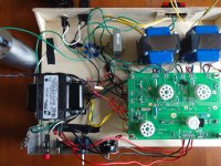
Is there anything visible in pics that would be questioned?
Would that lower the voltage at tube heaters? I'm not understanding why those voltages were other than 5 or 6.3 volts.
Is there anything visible in pics that would be questioned?
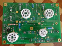
The 3 position terminal T1 near the rectifier tube you need to have the 2 red leads from the xformer on either end and the red/yellow CT wire in the middle.
The other 2 terminal T1 pads are for an Aux capacitor. I think you have your xformer hooked up wrong.
The other 2 terminal T1 pads are for an Aux capacitor. I think you have your xformer hooked up wrong.
Would that lower the voltage at tube heaters? I'm not understanding why those voltages were other than 5 or 6.3 volts.
Yes and no.
The heater on the 5AR4 has AC and DC on it - AC is 5 volt filament voltage; DC is rectified output voltage.
The other heaters have an elevating DC voltage applied to them. That is the purpose of R3, R4, and C3.
The AC readings will not change. The DC readings will go down.
Win W5JAG
The 3 position terminal T1 near the rectifier tube you need to have the 2 red leads from the xformer on either end and the red/yellow CT wire in the middle.
The other 2 terminal T1 pads are for an Aux capacitor. I think you have your xformer hooked up wrong.
I'm not following - it looks OK to me - he has the two high voltage windings at the rectifier, and the ct to the ground pad. That's how I do it.
I'm not sure about the soldering - I tend to use more, if some of these holes need solder to plate through to one side from the other, there could be some problems.
Win W5JAG
no he has the CT going to the Aux Capacitor pads...the 3 pad T1 terminals should be RED(HV) RED/YEL(CT) RED(HV)

Last edited:
I don't think that anything should be connected to that centre terminal on T1 red. It's to keep the 2 high voltages separate, the ct should be connected to the T1 res/yellow 2 terminal connector above along with the negative of the aux cap or . The transformer wiring looks ok to me.
you can tape off the HV CT wire if you want but it SHOULD NOT be connected to the AUX capacitor pad
Yes. there are 2 pairs of red wires so it's hard to tell which iare the HV but I presume those ones are from a rectifier switch. The aux Cap pads are the top ones with black wires.
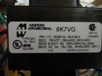
There is only one pair coming from the 6K7VG and they are the HV voltage.
The other red pair are poking out from one of the OPT's or a switch he has installed for SS vs Tube rectifier
The other red pair are poking out from one of the OPT's or a switch he has installed for SS vs Tube rectifier
Then that part of the board has been changed? You can see my SSE in the removing MOSFET's thread - I have mine as he has done. It is the first version of the board.
Win W5JAG
Win W5JAG

- Home
- More Vendors...
- Tubelab
- SSE first build, caps and other questions.