Hi Guys!
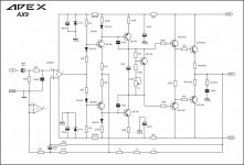
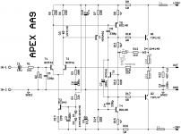
Hey Guys! I present my AX9 plan. I hope I did not went wrong.
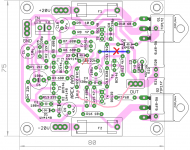
The Plan: http://www.kephost.com/images/2017/03/20/apex.jpg
Dear Hilion,
Kindly post the circuit diagram also along with the PCB lay out. It will be quite difficult to search in the long thread for the relevant diagram !
--gannaji
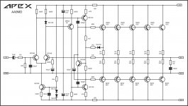
AX9 Schematic
Hello!
I attach the schematic!
Dear Hilion,
Kindly post the circuit diagram also along with the PCB lay out. It will be quite difficult to search in the long thread for the relevant diagram !
--gannaji
Hello!
I attach the schematic!
Attachments
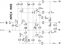
AA9 class A amplifier.
Mr. Mile,
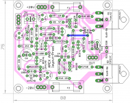
Just a quick layout (couldn't resist the itch to do a layout), PCB size not optimized..
Question: should R4 be connected to the ground through i/p ground traces or decoupling ground traces?
Reg
Prasi
Attachments

Mr. Mile,
Just a quick layout (couldn't resist the itch to do a layout), PCB size not optimized..
Question: should R4 be connected to the ground through i/p ground traces or decoupling ground traces?
Reg
Prasi
Nice work... connect R4 to +20V rail not to gnd it is my mistake.
You can also try to made AA14 pcb .
Regards
Nice work... connect R4 to +20V rail not to gnd it is my mistake.
You can also try to made AA14 pcb .
Regards
Yes Mr. Mile, I will do AA14 layout over the weekend.
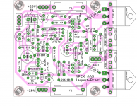
here is the corrected AA9 sch and layout.. if anyone wants to try, I shall post pdf's.
The BD's are inline and can take a small plate as heatsink and T6 can also be stuck to the same plate...
reg
Prasi
Attachments
i have 4 pairs of 2sc3855/2sa1491 and i would like to use it in apex ax16.,can anybody share the foil pattern, thanks in advance
Mr. Mile,
Just a quick layout (couldn't resist the itch to do a layout), PCB size not optimized..
Question: should R4 be connected to the ground through i/p ground traces or decoupling ground traces?
Reg
Prasi
Nice work Prasi. Good to see you back in the saddle with designs here.
Thanks.
Nice work Prasi. Good to see you back in the saddle with designs here.
Thanks.
Thanks x, yes this is the 'home thread'🙂.
What are R11 and D4 doing here?
Best regards!
Set bias at 1,6A this is class A amplifier.
Regards
Yes Mr. Mile, I will do AA14 layout over the weekend.
here is the corrected AA9 sch and layout.. if anyone wants to try, I shall post pdf's.
The BD's are inline and can take a small plate as heatsink and T6 can also be stuck to the same plate...
reg
Prasi
Nice work... you don't need jumper.
Regards
Attachments
Set bias at 1,6A this is class A amplifier.
Regards
Could a pot be used to adjust bias and what is preventing thermal runaway - or is it not an issue?
Could a pot be used to adjust bias and what is preventing thermal runaway - or is it not an issue?
You can replace 2k2 resistor (in series with 1N4148 diode) with pot and set bias. Thermal runaway is not an issue in class A.
Regards
Nice work... you don't need jumper.
Regards
You can replace 2k2 resistor (in series with 1N4148 diode) with pot and set bias. Thermal runaway is not an issue in class A.
Regards
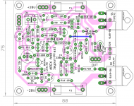
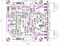
Mr. Mile, here is the revised layout. I have added pot after 1N4148 diode to set bias. Also made provision for non-inductive resistor BPR56 or normal wirewound and 250 volt film cap for zobel.
reg
Prasi
Attachments

Last edited:
Mr. Mile, here is the revised layout. I have added pot after 1N4148 diode to set bias. Also made provision for non-inductive resistor BPR56 or normal wirewound and 250 volt film cap for zobel.
reg
Prasi
Nice, but I suggest use 1k pot in series with 1k2 resistor instead 4k7 pot or just use 2k2 pot instead 4k7.
Regards
Last edited:
Nice, but I suggest use 1k pot in series with 1k2 resistor instead 4k7 pot or just use 2k2 pot instead 4k7.
Regards
here you go! still many things to learn from you..Mr. Mile, have you simmed this amp?, interesting to see the sim..
Attachments
Last edited:
Nice that TIP142/TIP147 are only $1.42/$1.76 at Mouser. Don't have to worry about fake 2SC5200/2SA1943's. This could be a fun cost-effective little class A amp. Just throw a set into my next order. I have all the other parts already on hand. A pdf layout for laserprinting would be perfect for a project like this once you work the bugs out Prasi.
Thanks,
X
Thanks,
X
Mays I ask you why you didn't use a diode connected BD140 in the negative half of your bias circuitry - just for symmetry reasons?
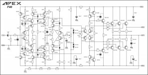
And what's the difference to your A40 design?
And which supply voltages do you recommend?
Best regards!
And what's the difference to your A40 design?
And which supply voltages do you recommend?
Best regards!
- Home
- Amplifiers
- Solid State
- 100W Ultimate Fidelity Amplifier