Slightly off topic.
I did not realise that there is actually an optical phono cartridge as product.
DS002 ?NEW?
It is not ridiculously expensive.
Patrick
I'm not thrilled with the technology write up. There is little or no evidence to support significant electro-mechanical coupling in the operation of a normal MM/MI cartridge. There is nothing here that substantially differentiates this from a strain gauge cartridge which in full bridge are very linear and can be inherently low noise.
Slightly off topic. I did not realise that there is actually an optical phono cartridge as product.
I have one here, and it sounds very good.
Did you use their standard electronics, or your own ?
According to Stereophile, their EQ electronics has too much bass.
Patrick
According to Stereophile, their EQ electronics has too much bass.
Patrick
Last edited:
It was probably something silly like a not-shorted winding during bellringer tests, caused by an alligator clip that slipped off, or a piece of masking tape that came loose.
Well, I scrutinized my measurement results of Nov. 2015 today and found no reason to fault them (http://www.diyaudio.com/forums/powe...rmer-snubber-using-quasimodo-test-jig-74.html, Post #740).
I also repeated the measurements with the same transformer (Triad FS24-800) as follows:
- Natural frequency with Quasimodo (primary and one secondary shorted), got 88kHz; cross-checked by exciting the secondary with 10nF in parallel with a loosely coupled RC sine generator. Maximum voltage found at 88.5kHz, the same result as above and slightly higher than in the Table posted previously in this thread (86.2kHz, probably due to a different 10nF capacitor now in the ringer).
- Parasitic ringing with the transformer feeding a bridge of four 1N4004 diodes followed by 1000uF electrolytics, bipolar DC output of +-12V (nominal), loaded by 330R resistors. The same oscillation frequency of 26kHz as in post#740 above, i.e. not equal to the value obtained with the ringer.
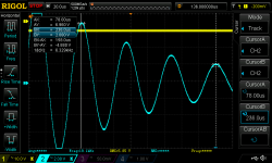
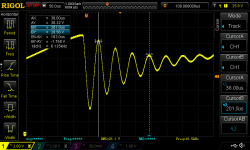
However, all three transformers I measured are of the centre-tapped type, whereas Mark measured three single-secondary transformers. So I connected the Triad FS24-800 in a single-secondary configuration, i.e. 24V instead of 2x12V, to the ringer and got a natural frequency of 19kHz (1st attachment).
Now came the surprise: the ringing frequency of this configuration did not change when the 24V secondary was driving the same 1N4004 bridge as before, i.e. this transformer now behaved the same as the three ones measured by Mark (2nd attachment).
As we see, the parasitic inductance of the same transformer changed by a factor of almost five when measured over both secondary windings with respect to the value obtained by measuring with one winding only.
I did not have time today to repeat this last measurement with the other two transformers with centre-tapped secondaries I've got, but I think it is reasonable to expect the same behaviour.
While I think that a higher value of the parasitic inductance should be expected when both windings are active, my modest knowledge of the Electromagnetics does not allow me to go further than that.
Regards,
Braca
Attachments
Since ringing period is proportional to sqrt(L) as shown in #91155, your transformer leakage inductance appears to have changed by a factor of twenty one (!!)As we see, the parasitic inductance of the same transformer changed by a factor of almost five when measured over both secondary windings with respect to the value obtained by measuring with one winding only.
- 1/sqrt(L_before) = constant * 88 kHz
- 1/sqrt(L_after) = constant * 19 kHz
- L_after / L_before = (88/19)^2 = 21.45
full-up coupling and leakage models of transformers aren't trivial: http://www.denverpels.org/Downloads/Denver_PELS_20070410_Hesterman_Magnetic_Coupling.pdf
Leakage Inductance Measurement Tips
• Avoid measuring inductance close to self-resonant frequencies
• Winding resistances decrease the measured coupling coefficients when
using the self and leakage inductance method
• Measure at a frequency where the Q is high
(It doesn’t have to be at the operating frequency)
• For each pair of windings, shorting the winding with the highest Q gives the best results.
That was a nice presentation, thanks very much for linking it here. It appears the Cantilever model is a bit simpler than the transformer model in Cristophe Basso's books.
I used theirs, and had no complaints about the bottom end.
You have a different version than Fremer did. It did sound pretty interesting but the whole system was new.
Thank you for your comment - I wrote "parasitic inductance" where I meant to write "frequency". Sort of a "late night" mistake.Since ringing period is proportional to sqrt(L) as shown in #91155, your transformer leakage inductance appears to have changed by a factor of twenty one (!!)
That is indeed a surprise. Are you able to see any difference at all between the two cases, in SPICE simulation? When I simulated circuits like yours in August 2013, I was not.
- 1/sqrt(L_before) = constant * 88 kHz
- 1/sqrt(L_after) = constant * 19 kHz
- L_after / L_before = (88/19)^2 = 21.45
I haven't simulated any of the transformers I measured. Having read the Morgan Jones' article in Linear Audio Vol. 5, the effort required for obtaining an accurate transformer model put me off.
Regards,
Braca
If the two halves of the center tapped secondary are identical or nearly identical then I would expect that any discrepancies between bellringer testing and actual operation, would either be a factor of two difference in inductance {giving a factor of 1.4 difference in frequency} or a factor of four difference in inductance {giving a factor of 2.0 difference in frequency}. Either
- You expected one inductor of L henries but you got a series circuit of two L henry inductors, (factor of 2) or
- You expected two L henry inductors in parallel but you got two L henry inductors in series (factor of 4)
Everybody's gone for a beer or two ?!?
I do not think so, that is what makes them talking 🙂

I was planning on building a copy! The basic buffer circuit I built sounds quite nice, measures decently also. Not too worried about the power supply. Volume control will not be a copy more likely a stepped attenuator. More of a question what selector switch to use. No problem with cyro'd silver wire. But will probably form it before treatment.
No problem with cyro'd silver wire. But will probably form it before treatment.
And we all know you can mill the case out of a solid billet of Al. The MIT science fiction society had a rather large chunk of titanium sitting around, it was amazing when you could just pick it up while thinking it was 100lb of iron.
Last edited:
- Status
- Not open for further replies.
- Home
- Member Areas
- The Lounge
- John Curl's Blowtorch preamplifier part II